Rotary sealing device

a sealing device and rotary technology, applied in the direction of machines/engines, braking systems, positive displacement liquid engines, etc., can solve the problems of accelerating packing wear, corresponding wear of the mating rod surface, and artificial lift pumps in the cavity day progressing

Inactive Publication Date: 2003-11-06
KALSI ENG INC A TEXAS PARTNERSHIP
View PDF43 Cites 37 Cited by
  • Summary
  • Abstract
  • Description
  • Claims
  • Application Information

AI Technical Summary

Benefits of technology

[0009] An objective of the present invention is to provide a rotary seal cartridge for progressing cavity artificial lift pump drive heads which is readily adaptable to existing pumps and which provides longer maintenance intervals and service life, and accommodates higher pressure, compared to the conventional stuffing box sealing arrangements now used.
[0010] Another feature of the present invention is a bearing guided sleeve which rotates in unison with the polished rod, and provides a smooth, hardened, true running, abrasion resistant running surface for the rotary seals. By maintaining a constant, non-varying seal extrusion gap, this true-running sleeve preserves the life of the rotary seals by minimizing extrusion damage. This sleeve surrounds the polished rod, but runs true on it's own bearings and does not follow the dynamic run out and vibration induced lateral motion of the polished rod. The exceptionally true running characteristic of the sleeve is insured by (1) exploitation of the hydrostatic force of the pressure of the crude oil process fluid to preload one of the bearings in a way that eliminates internal bearing running clearance, (2) by spring loading of the opposite bearing in a way that eliminates internal bearing running clearance while accommodating differential thermal expansion, and in a way that simultaneously prevents slippage of the inner race and thereby eliminates wear and increased internal clearance that would otherwise result from said slippage, and (3) by axial clamping of the outer bearing races so that the necessary installation clearance between the outer race and the housing bore cannot contribute to dynamic run out. The clamping arrangement also makes the outer races immune from spinning within the housing bore in the event that bearing torque increases due to damage to the bearing running surfaces.
[0013] The contaminant pressure acts on the second surface area and develops a lubricant pressure within the lubricant supply chamber which is different from contaminant pressure. Preferably the lubricant pressure is amplified above contaminant pressure so that the lubricant pressure within each of the lubricant chambers between the housing and rotary element establishes a pressure differential acting toward the lower pressure contaminant or environment. The higher lubricant pressure serves to hold the rotary seals straight, preventing skew-induced wear of the seals. Moreover, since the seals are preferably hydrodynamic seals, the higher lubricant pressure acts to enhance the wedging effect of the lubricant into the dynamic sealing interface between the seals and the rotary member by preventing process fluid pressure induced distortion of the hydrodynamic geometry of the seal.

Problems solved by technology

One significant remaining weakness of present day progressing cavity artificial lift pumps has been the conventional stuffing box arrangement provided to seal-off the relatively rotating rod string as it enters the yoke area.
In many stuffing box applications such as low pressure pumps for non-abrasive liquids, lubrication provided by leakage contributes significantly to the life of the packing, but in the progressing cavity artificial lift pump, the leakage contains abrasives which accelerate packing wear, and cause corresponding wear of the mating rod surface.
Adjusting the packing ring gland follower to control leakage is a matter of judgment, and over-tightening can cause high interfacial contact pressures which cause rapid packing failure, resulting in significant crude oil leakage.
Unfortunately, however, the surface of the polished rod quickly becomes damaged from handling and environmental exposure in ways that promote severe packing wear.
For example, polished rod corrosion scale, pitting, and impact damage can be very detrimental to packing life.
The drive heads of many progressing cavity artificial lift pumps permit significant dynamic run out of the polished rod, often in conjunction with severe rod string vibration.
Such dynamic lateral shaft motion is difficult for any rotary sealing system to accommodate, and tends to wallow out the stuffing box packing and produce unacceptable crude oil leakage.
Misalignment between the bearing housing and the stuffing box can also be a concern by creating uneven radial loading of the packing.

Method used


Image

  • Rotary sealing device
  • Rotary sealing device
  • Rotary sealing device

Examples


Embodiment Construction

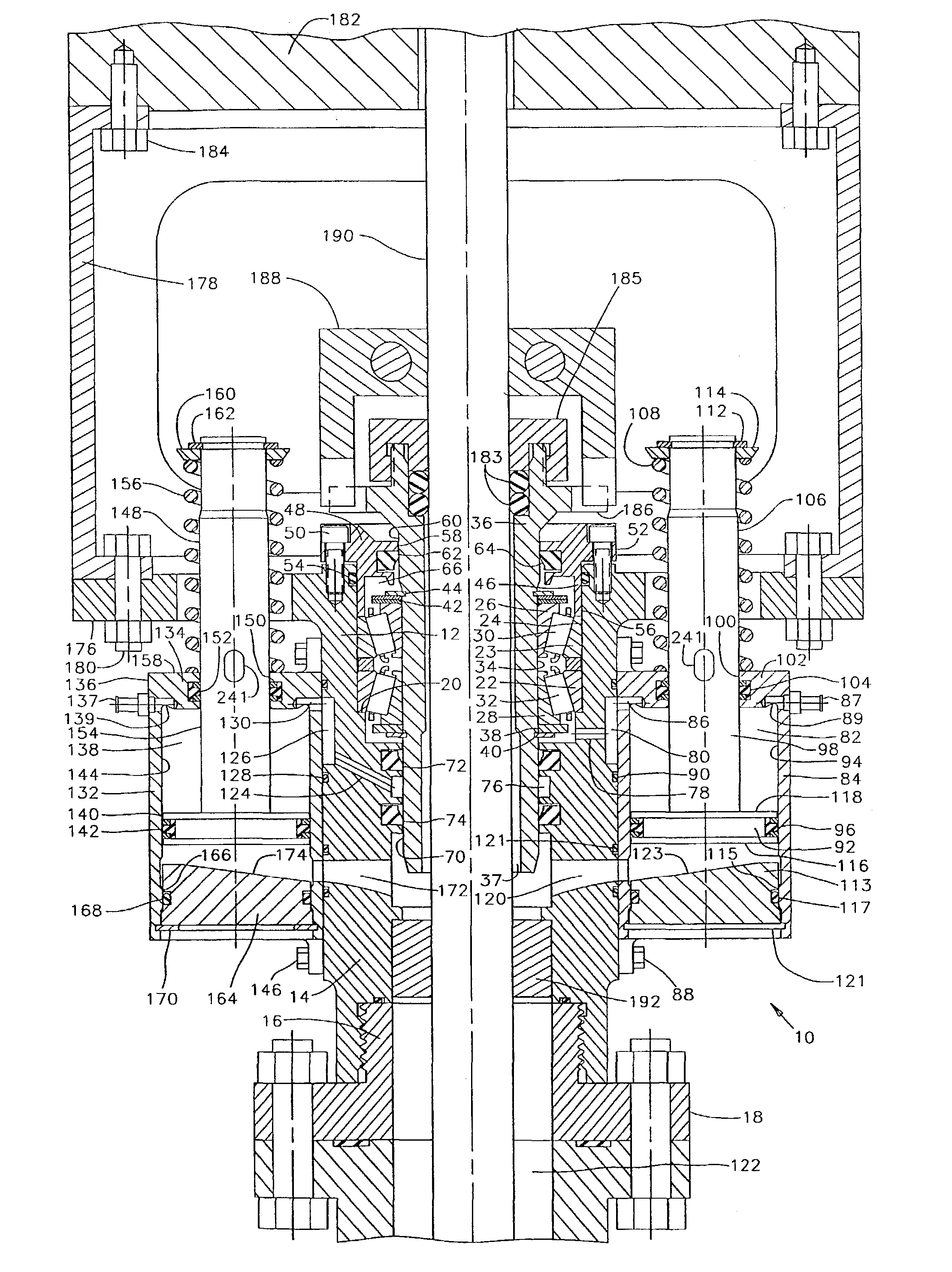
[0032] Though the present invention is discussed herein particularly as it relates to rotary drive mechanisms for progressing cavity pumps, such discussion is not intended to limit the spirit and scope of the invention. The invention will also be found to have merit in any apparatus where a driven rotary shaft penetrates a vessel, reservoir, or other structure and is in contact with or contains a liquid so that a seal mechanism is required to contain the liquid and to protect portions of support means which may be in the form of a apparatus from contamination.

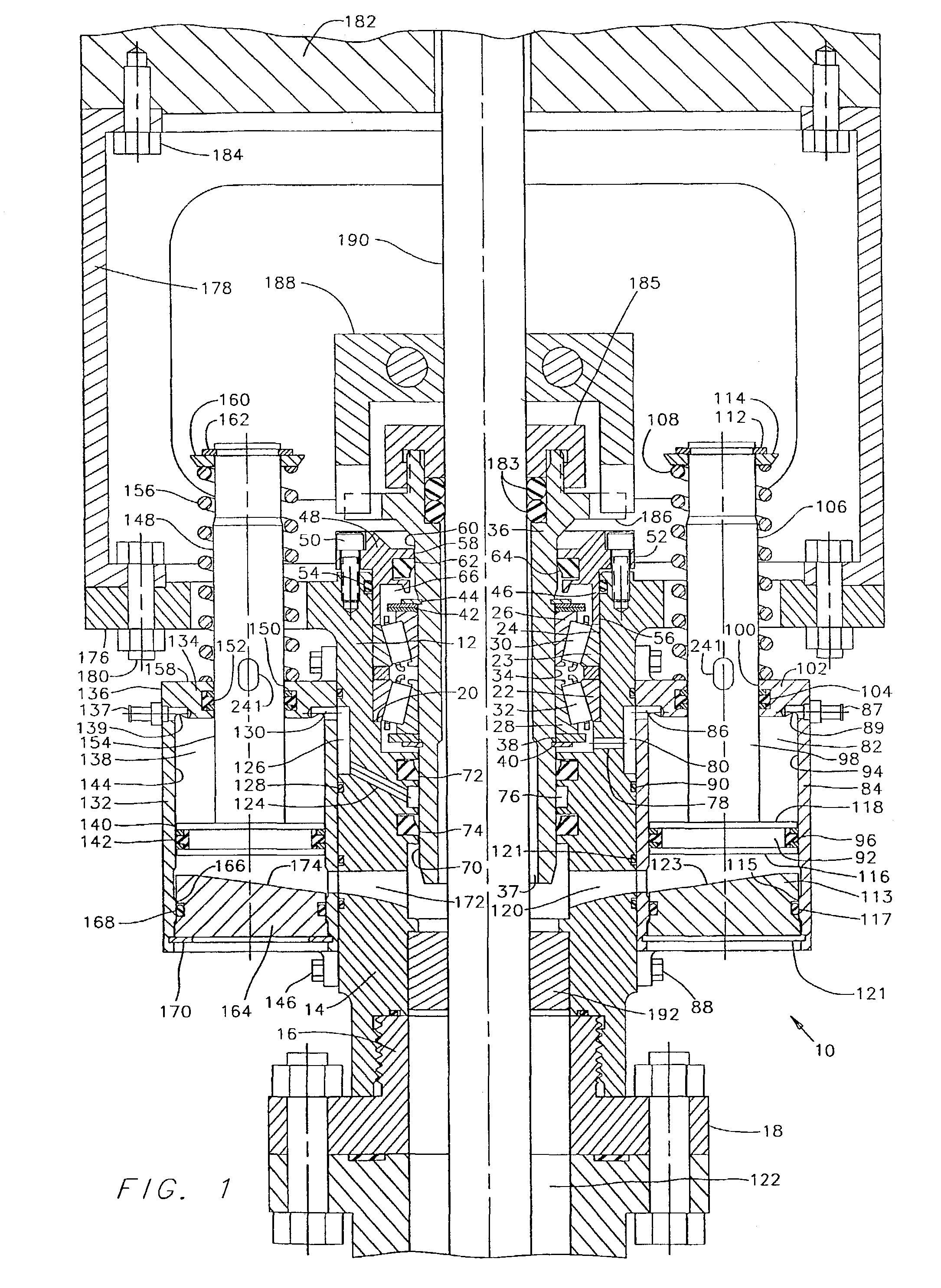
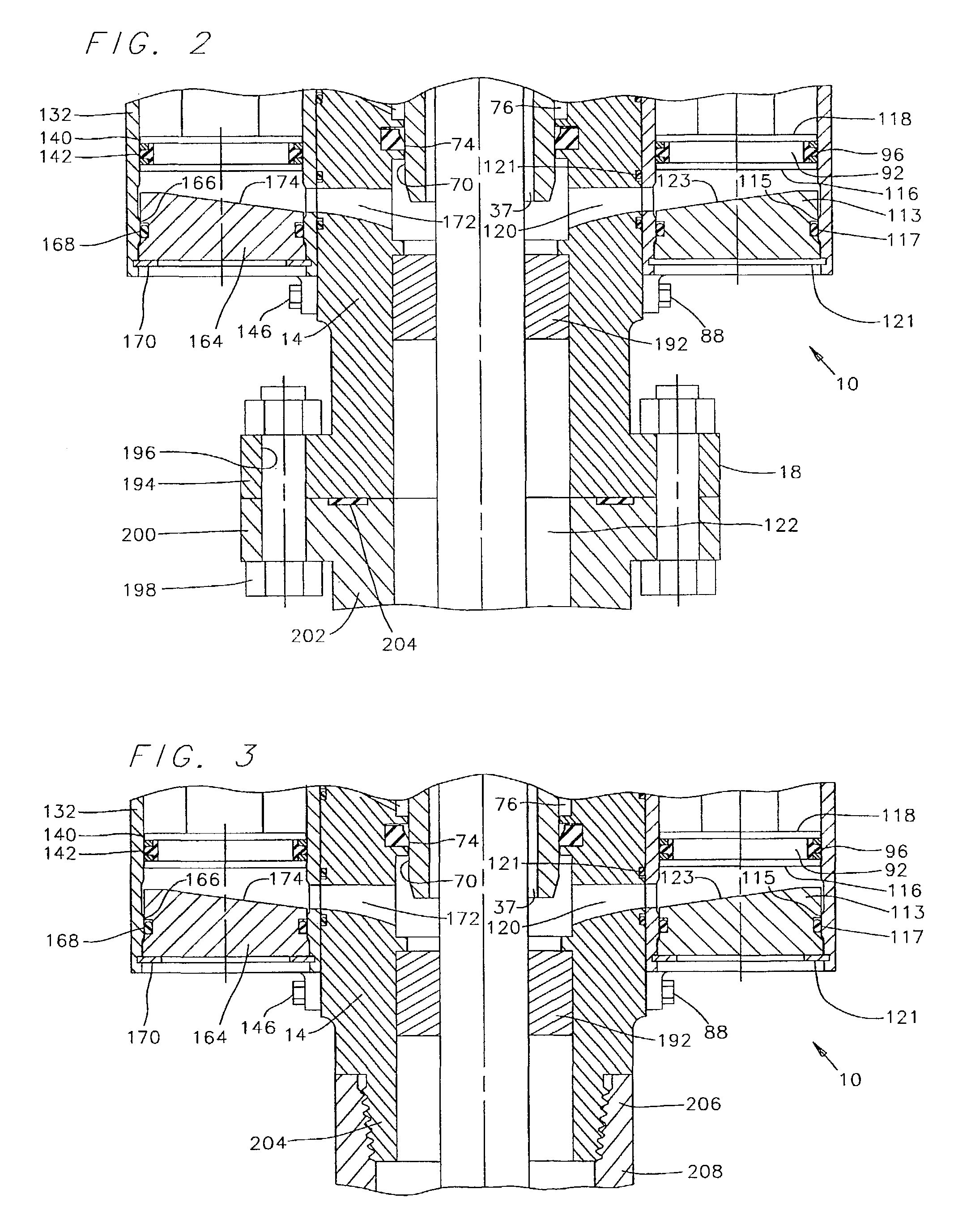
[0033] Referring now to the drawings and first to FIG. 1, a contaminant pressure responsive, lubricant pressure amplified rotary rod seal cartridge, such as is employed for rotary well pumps, such as rotary progressing cavity pumps, is shown generally at 10. The rotary rod seal cartridge 10 has a bearing and seal carrying housing 12 which is adapted at its lower end 14 for threaded assembly with a cartridge mounting base 16 whi...


PUM


Abstract

A contaminant pressure responsive, lubricant pressure amplified or modified rotary seal cartridge for rotary well pumps and other rotary mechanisms. A housing member having a passage subject to contaminant pressure, has a rotary wear sleeve which is supported by bearings and is sealed to the housing by a plurality of spaced seals which define at least one and preferably two or more lubricant chambers for bearing lubrication and for hydrodynamic sealing. Lubricant pressure amplification cylinders are in fluid communication with respective lubricant chambers. Pistons moveable within each of the cylinders define differential surface areas exposed to lubricant and to contaminant pressure. Contaminant pressure acts on the pistons and develops lubricant pressure which is different, preferably higher, but can be lower than contaminant pressure. When lubricant pressure is higher than contaminant pressure it acts directionally toward contaminant pressure or environment pressure to minimize the potential for contaminant intrusion into the lubricant chambers and also enhances the hydrodynamic wedging of the lubricant into the dynamic sealing interface between the seals and the rotary member for enhanced service life of the seals even under high pressure conditions.

Description

[0001] 1. Field of the Invention[0002] The present invention relates generally to rotary sealing devices for hydrodynamically lubricated sealing between relatively rotating members. More specifically, the present invention concerns rotary cartridges for progressing cavity type artificial lift pumps, wherein such cartridges are provided with hydrodynamic sealing between relatively rotatable members, such as between a housing and a rotary sleeve or shaft and wherein the hydrodynamic seal or seals serve as one or more partitions between a contaminant environment and a lubricant. Even more specifically, the present invention concerns a contaminant pressure responsive, lubricant pressure amplified rotary rod seal cartridge for rotary shaft drive mechanisms, for establishing sealing at the shaft to reservoir interface and to prevent loss of process fluid from the oil and gas production reservoir. Also, the present invention concerns a rod seal cartridge for progressing cavity artificial l...

Claims


Application Information

Patent Timeline
Patent Type & Authority Applications(United States)
IPC IPC(8): F04B39/04F04B47/00
CPCF04B47/00F04B39/04
Inventor DIETLE, LANNIE LKALSI, MANMOHAN SHEIDT, GUNTHERCONROY, WILLIAM TGOBELI, JEFFREY DSCHROEDER, JOHN E
Owner KALSI ENG INC A TEXAS PARTNERSHIP
Why Eureka
Try Eureka