Blood filters, blood collection and processing systems, and methods therefore

a filter and blood collection technology, applied in the direction of multi-stage water/sewage treatment, instruments, separation processes, etc., can solve the problems of affecting the quality of blood collection, the filter is subjected to centrifugation, and the blood separation set cannot be easily applied to the filter, so as to achieve the effect of increasing the loss of raw materials

Inactive Publication Date: 2003-11-13
FENWAL +1
View PDF94 Cites 43 Cited by
  • Summary
  • Abstract
  • Description
  • Claims
  • Application Information

AI Technical Summary

Benefits of technology

[0013] It is an object of the present invention to provide a flexible blood processing filter without using a sheet type flexible frame, which eliminates the above drawbacks of complicated manufacturing process and increased loss of raw materials.
[0015] Accordingly, one object of the present invention is to provide a flexible blood treatment filter that with no use of a flexible frame to consequently avoiding a complicated manufacturing process or increase of loss of the starting materials.
[0016] Another object of the present invention is to provide a blood treatment filter that can prevent the medical workers from the risks of exposure to infections or the blood preparations from contamination with bacteria, even when the seal portions between the filter element and the vessel is broken to cause leakage by a mis-operation and rough handling during the filtration operation, and by stress during centrifugation.
[0018] Yet another object of the present invention is to provide a blood collection system comprising a container and an interconnected filter, which can be handled and centrifuged as a unit without breakage of the filter or damage to the container.

Problems solved by technology

While a filter comprising a filter medium made of a non-woven fabric or a porous material packaged in a hard vessel such as polycarbonate has been widely used for conventional white blood cell elimination filters, it was a problem that a steam sterilization process that is widely used for sterilization of the blood separation set can be hardly applied for the filter as described above since the vessel's gas permeability is low or practically nil.
In the latter case, however, the white blood cell elimination filter is subjected to centrifugation together with the blood collection and separation set, whereby the hard vessel may damage the bags and guide tubes or the hard vessel itself may be broken due to the stress caused by centrifugation.
However, the filter element should be once welded to a sheet of a flexible frame, followed by welding the frame to a housing material, in the white blood cell elimination filters as described above thus giving rise to a problem in that the manufacturing process becomes complicated.
It has been also a problem that a large portion of the starting material is wasted since an effective filtration port is ensured by punching the sheet inside of the frame.
Because of this, there is a risk of damage to the port itself to breakage by the stress generated during the centrifugation as in the past filter device including a rigid plastic housing.
The filter in the former patent publication 7-267871 also has some drawbacks, in that the risk of infection to medical workers or contamination of the blood preparation with bacteria could not be avoided when the welded part happens to be broken to cause leakage by mis-operation and tough handling during filtration operations or by the stress of centrifugation, because the outermost circumferential edges of the filter element is welded to the vessel material.
With this structure, if the weldings of the filter material and the vessel material are insufficient, it may not be easy to detect any leakage of the blood caused by such insufficient weldings.

Method used


Image

  • Blood filters, blood collection and processing systems, and methods therefore
  • Blood filters, blood collection and processing systems, and methods therefore
  • Blood filters, blood collection and processing systems, and methods therefore

Examples


example 2

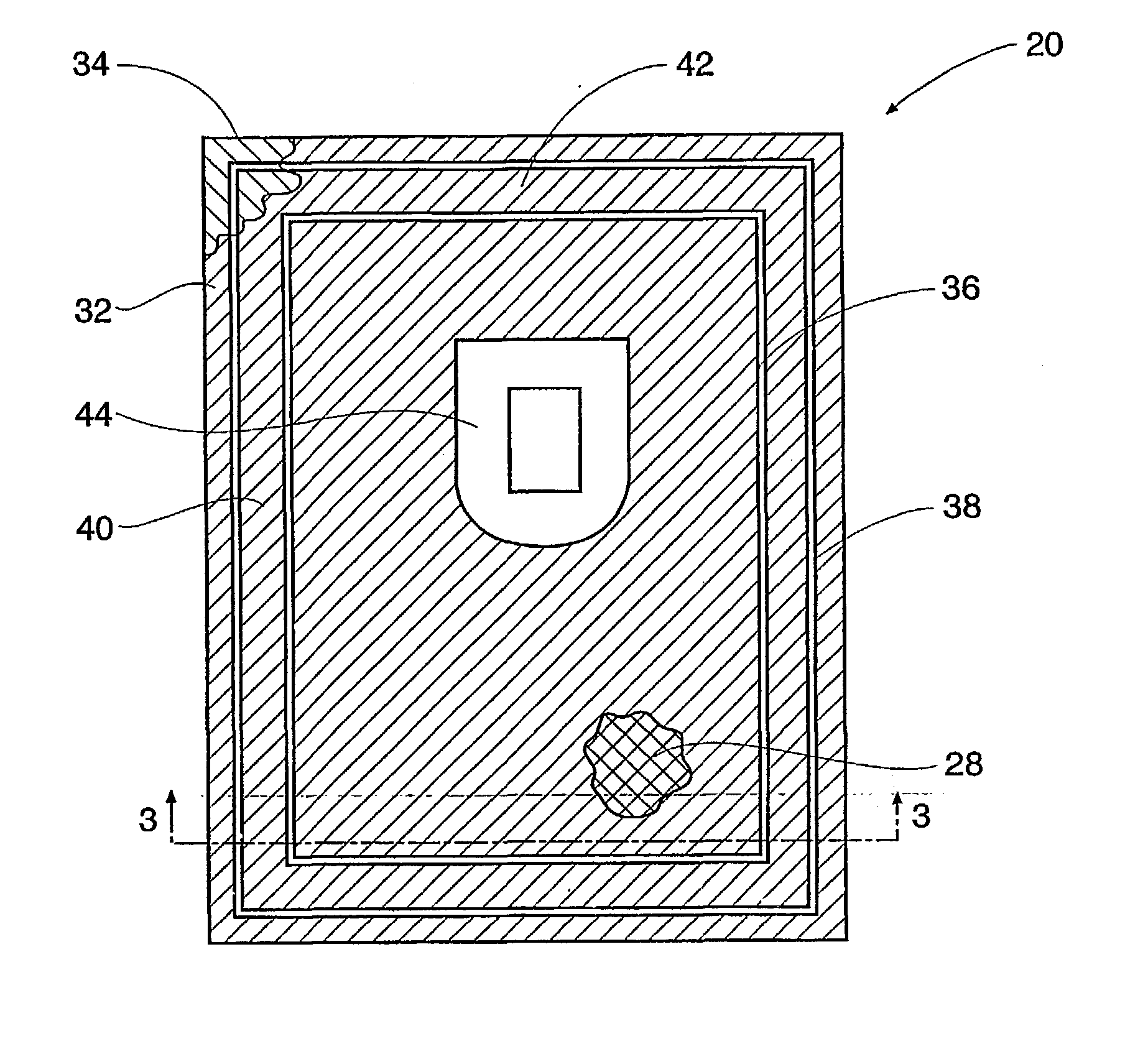
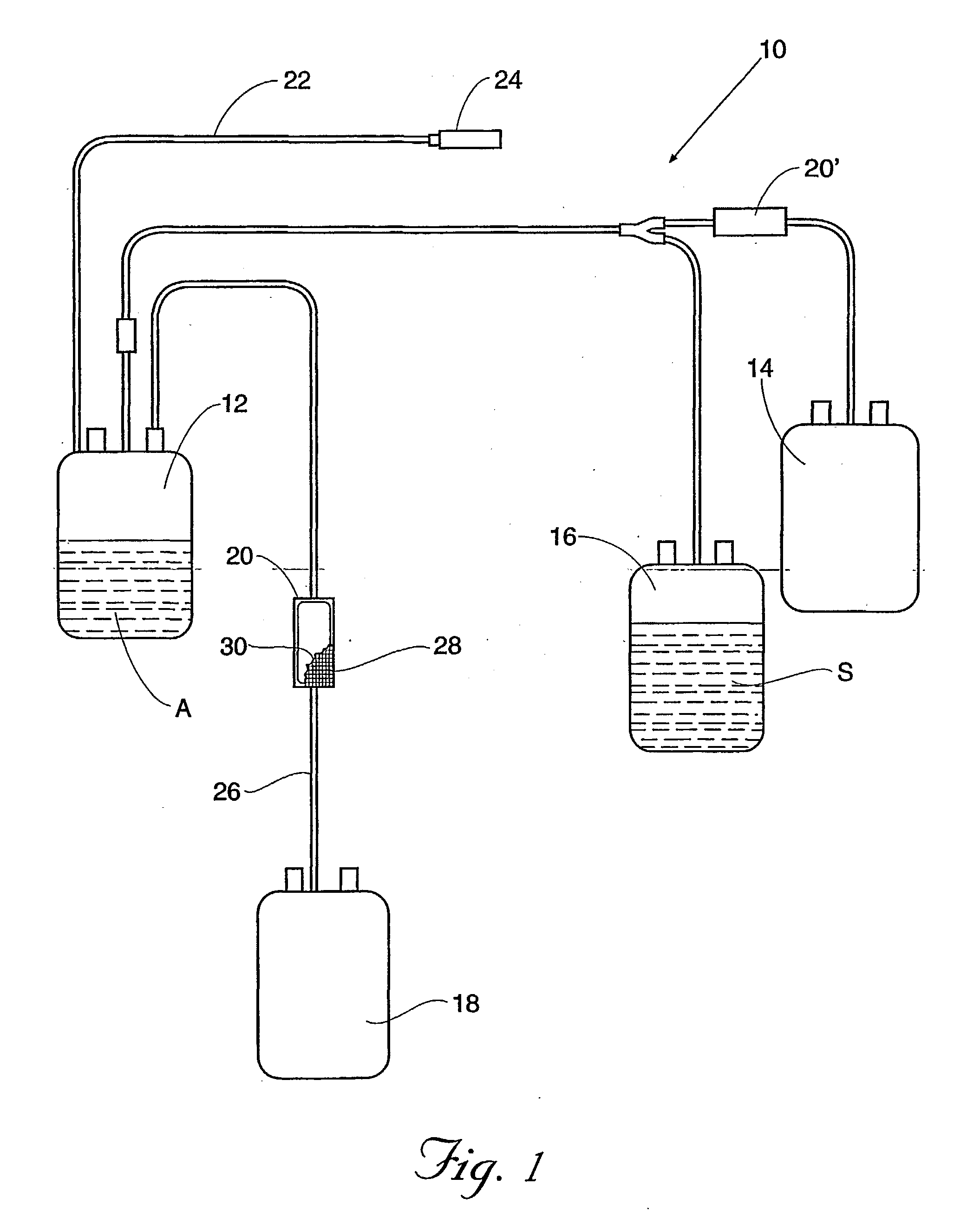
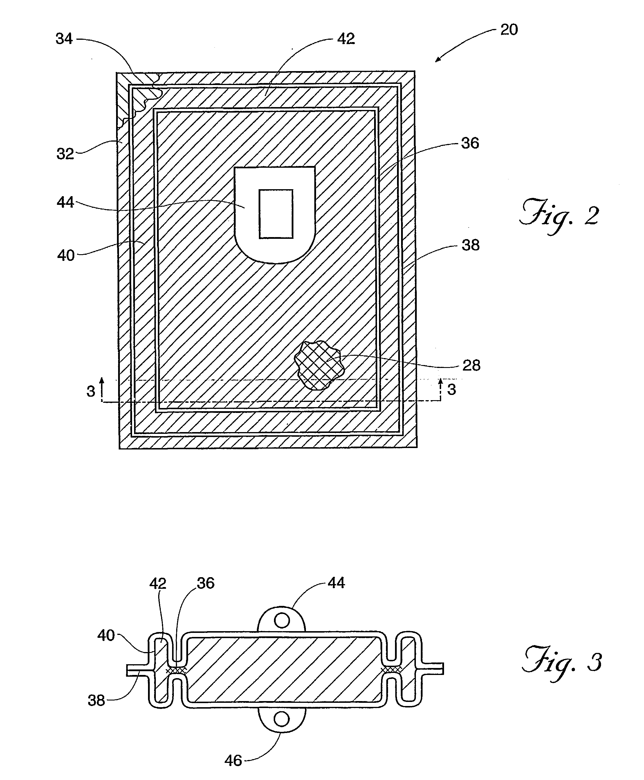
[0115] The filter element c was cut into a size of 82 mm.times.65 mm. The first seal area was welded so that the width of the protruding filter element g is 0.5 mm.

[0116] After subjecting the first seal portion to the leakage inspection, filters were manufactured by the same method as in Example 1, except that the flexible vessels b and d were welded so that the width of the non-seal area h is 1 mm. The results of the leakage test by the method described above are shown in TABLE 1.

example 3

[0117] Example 1 was followed except that the filter element was cut into 87.times.70 mm size so that the width of step-out portion (g) was 3 mm and the width of nonsealed area (h) was 6 mm. The difference between the greatest width and the smallest width of protruding filter element was 1 mm. The results of leak tests before and after sterilization / centrifugati-on are shown in Table 3.

example 4

[0118] Example 1 was followed except that the filter element was cut into 89.times.72 mm size so that the width of protruding filter element was 4 mm and the width of nonseal area (h) was 7 mm. The variation of the width of protruding element was 1 mm. The results of leak tests before and after sterilization / centrifugation are shown in Table 3.


PUM

PropertyMeasurementUnit
gap widthaaaaaaaaaa
widthaaaaaaaaaa
widthaaaaaaaaaa

Abstract

A blood collection system has a container for holding blood and a filter communicating with the container, mutually arranged for handling as a unit. The filter (20) contains a fibrous filter medium (28) housed within two flexible sheets (32, 34) of plastic. A first seal (36) joins the sheets (32, 34) directly to the filter medium (28) inboard of the peripheral edge (40) of the filter medium (28), and a second seal (38) joins the sheets (32, 34) outboard of the peripheral edge (40) of the filter medium (28). A region (42) of the filter medium (28) extends between the first and second seals (36, 38) to cushion contact with the filter housing during handling.

Description

[0001] The present invention generally relates to blood collection and processing filters, systems and methods for reducing the presence of or eliminating undesirable components such as aggregates and white blood cells (leukocytes) from blood. More particularly it relates to a precise and disposable blood treatment filter and systems incorporating such filters for eliminating minute aggregates and white blood cells from whole blood preparations, red blood cell preparations, platelet preparations and plasma preparations for use in blood transfusions. The present invention further relates to a blood treatment filter which is most suitable to be subjected to centrifugation for separating each blood component, wherein the filter itself is subjected to centrifugation along with the blood-containing bag and other components of the blood filter system.[0002] Systems composed of multiple, interconnected plastic bags have met widespread use and acceptance in the collection, processing and st...

Claims


Application Information

Patent Timeline
Patent Type & Authority Applications(United States)
IPC IPC(8): A61M1/02A61M1/36
CPCA61M1/3633A61M1/0218A61M2205/7545A61M2202/0439A61M1/0227
Inventor LYNN, DANIEL RWONS, ALLEN RMESPREUVE, LUCVANDENDAUL, DANIELSOUDANT, GREGORYMUI, TAT CKARLOVSKY, DANIEL MMURPHEY, RANDYCALHOUN, DARYL ROKA, SHIN-ICHIROHTSUJI, MICHIHIRO
Owner FENWAL
Why Eureka
Try Eureka