Optical recording medium and method for optically recording data in the same

a recording medium and optical recording technology, applied in optical recording/reproducing/erasing methods, mechanical recording, instruments, etc., can solve the problems of laser beams affecting the surface of the second recording layer, difficult to form a layer, and difficult to improve long-time storage reliability

Inactive Publication Date: 2003-12-18
TDK CORPARATION
View PDF30 Cites 18 Cited by
  • Summary
  • Abstract
  • Description
  • Claims
  • Application Information

AI Technical Summary

Problems solved by technology

However, since an organic dye is degraded when exposed to sunlight or the like, it is difficult to improve long-time storage reliability in the case where an organic dye is used as the material of the recording layer.
As a result, it becomes difficult to form a layer such as a recording layer on the light transmission layer as is done in conventional optical recording media such as the CD and DVD.
On the other hand, increasing concern about global atmospheric problems further makes it necessary to fabricate optical recording media with materials put minimal load on the environment.
However, in an optical recording medium including a first recording layer and a second recording layer sequentially formed on a substrate by a gas phase growth process and constituted to be irradiated by a laser beam projected onto the side opposite from the substrate, the laser beam impinges on the surface of the second recording layer, which has poor surface smoothness because it is formed by a gas phase growth process on

Method used


Image

  • Optical recording medium and method for optically recording data in the same
  • Optical recording medium and method for optically recording data in the same
  • Optical recording medium and method for optically recording data in the same

Examples


working example 1

[0121] An optical recording medium was fabricated in the following manner.

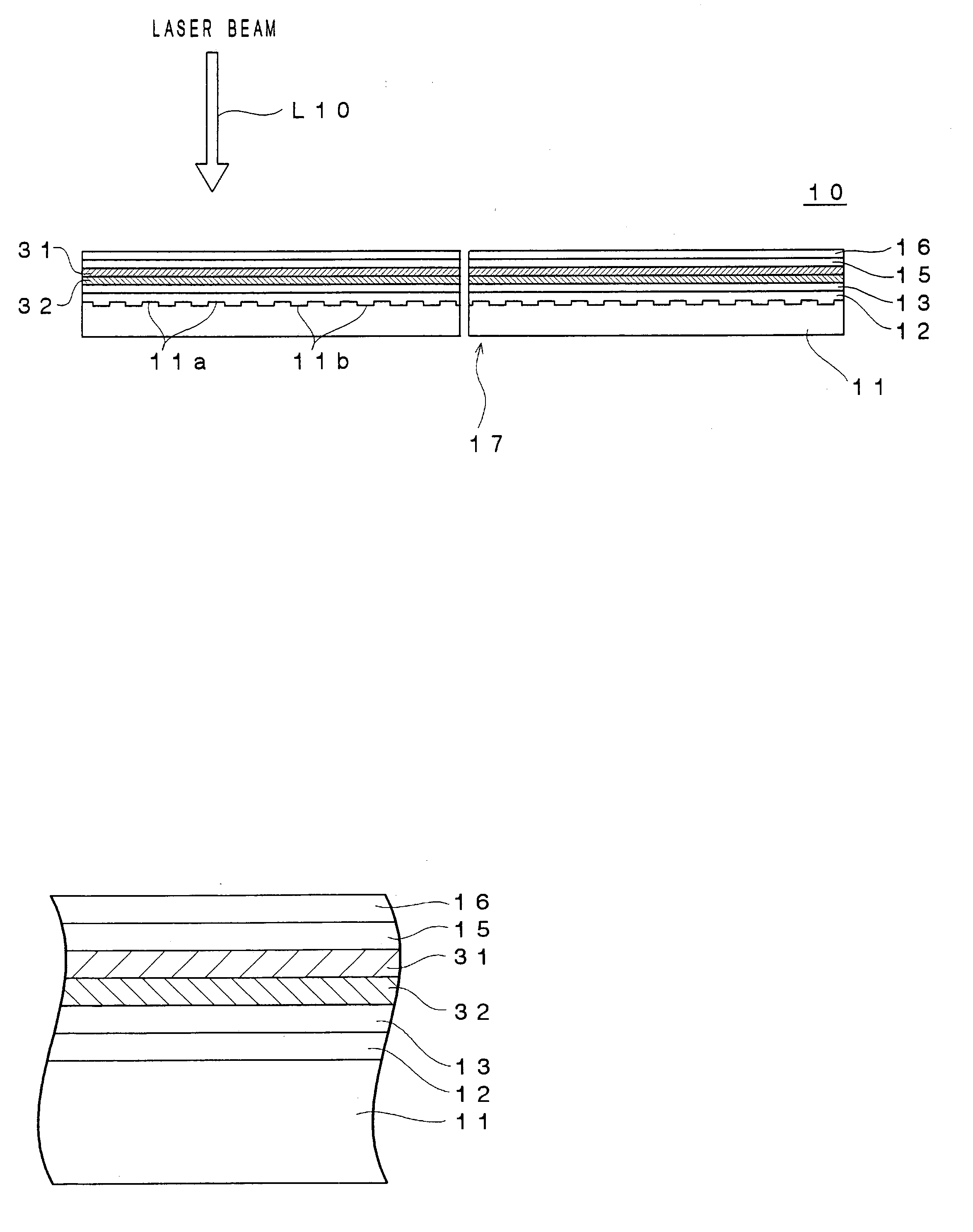
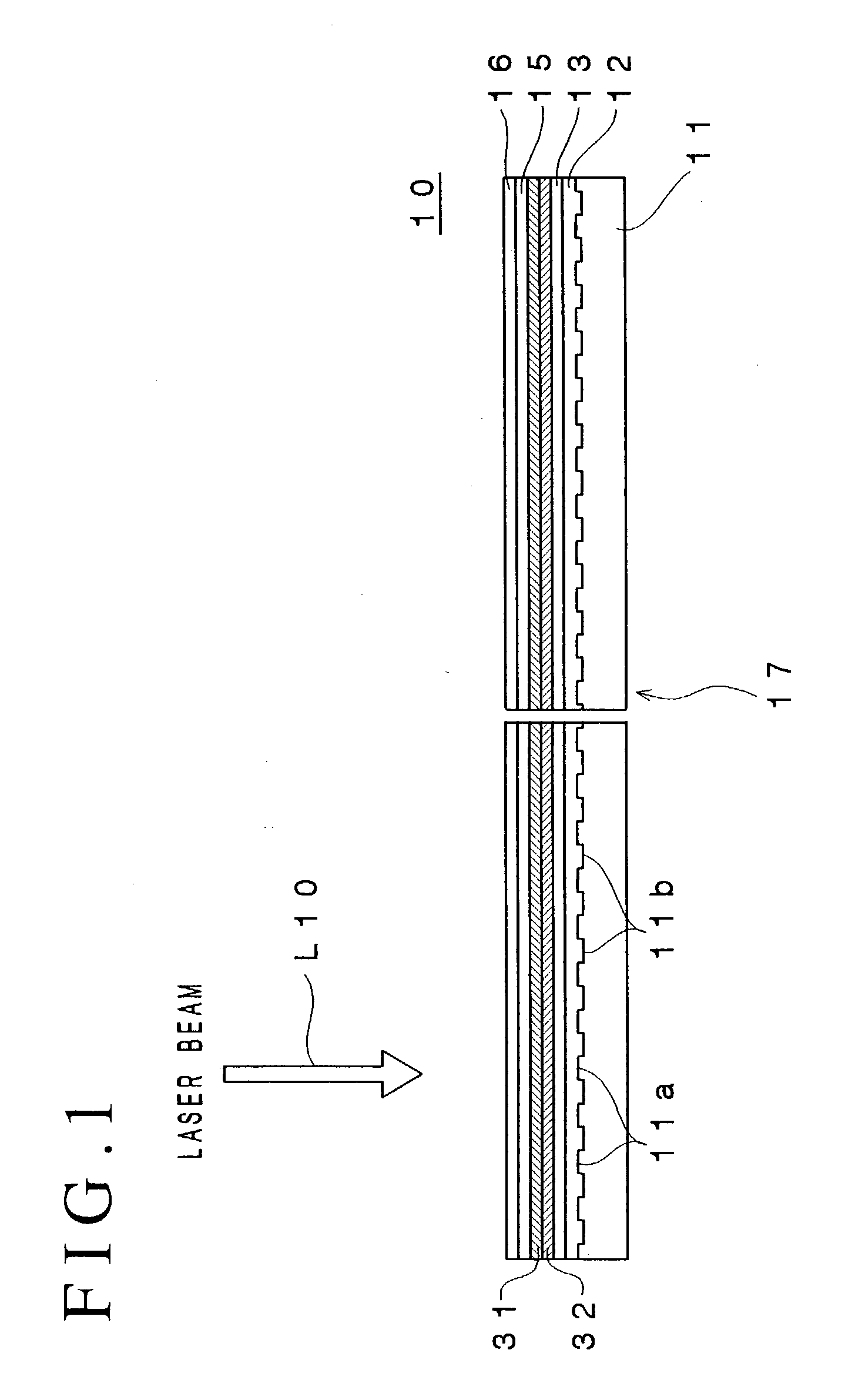
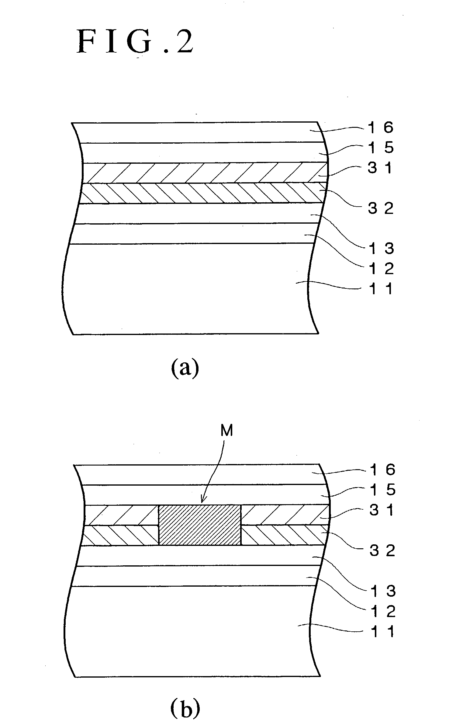
[0122] A polycarbonate substrate having a thickness of 1.1 mm and a diameter of 120 mm was first set on a sputtering apparatus. Then, a reflective layer containing the mixture of Ag, Pd and Cu and having a thickness of 100 nm, a second dielectric layer containing a mixture of ZnS and SiO.sub.2 and having a thickness of 28 nm, a second recording layer containing Zn as a primary component and having a thickness of 4 nm, a first recording layer containing Si as a primary component and having a thickness of 8 nm and a first dielectric layer containing the mixture of ZnS and SiO.sub.2 and having a thickness of 22 nm were sequentially formed on the polycarbonate substrate using the sputtering process.

[0123] The mole ratio of ZnS to SiO.sub.2 in the mixture of ZnS and SiO.sub.2 contained in the first dielectric layer and the second dielectric layer was 80:20.

[0124] Further, the first dielectric layer was coated using...

working example 2

[0127] Optical recording medium samples #2-1 to #2-3 were fabricated in the manner of Working Example 1, except that a first recording layer containing Ge as the primary component was formed.

working example 3

[0128] Optical recording medium samples #3-1 to #3-3 were fabricated in the manner of Working Example 1, except that a first recording layer containing C as the primary component was formed.


PUM


Abstract

An optical recording medium includes a substrate, a first recording layer formed on the substrate and containing an element selected from the group consisting of Si, Ge, C and Al as a primary component, and a second recording layer located in the vicinity of the first recording layer and containing Zn as a primary component, the optical recording medium being constituted to be irradiated by a laser beam projected onto the side opposite from the substrate and the total thickness of the first recording layer and the second recording layer being equal to or thinner than 30 nm. According to the thus constituted optical recording medium, it is possible to decrease a noise level and improve a C/N ratio in a reproduced signal.

Description

[0001] The present invention relates to an optical recording medium and a method for optically recording data in the optical recording medium and, particularly, to an optical recording medium constituted so as to record data therein and reproduce data therefrom by projecting a laser beam onto the side opposite from a substrate, which includes two or more recording layers and is capable of decreasing noise level and improving C / N ratio of a reproduced signal, and a method for optically recording data in the same.DESCRIPTION OF THE PRIOR ART[0002] Optical recording media such as the CD, DVD and the like have been widely used as recording media for recording digital data. These optical recording media can be roughly classified into optical recording media such as the CD-ROM and the DVD-ROM that do not enable writing and rewriting of data (ROM type optical recording media), optical recording media such as the CD-R and DVD-R that enable writing but not rewriting of data (write-once type ...

Claims


Application Information

Patent Timeline
IPC IPC(8): G11B7/00G11B7/004G11B7/0045G11B7/24035G11B7/243G11B7/258
CPCG11B7/24035G11B7/243G11B7/258G11B2007/24328G11B2007/24308G11B2007/2431G11B2007/24312G11B2007/24304G11B7/24038G11B7/0045
Inventor MISHIMA, KOJIAOSHIMA, MASAKIINOUE, HIROYASUHIRATA, HIDEKIUTSUNOMIYA, HAJIME
Owner TDK CORPARATION
Why Eureka
Try Eureka