Integrated palladium-based micromembranes for hydrogen separation and hydrogenation/dehydrogenation reactions

a technology of hydrogen separation and hydrogenation, applied in the field of separation membranes, can solve the problems of large volumes of stored hydrogen gas, difficult hydrogen storage for portable or mobile power sources, and high cost of hydrogen storag

Inactive Publication Date: 2004-02-12
MASSACHUSETTS INST OF TECH
View PDF0 Cites 26 Cited by
  • Summary
  • Abstract
  • Description
  • Claims
  • Application Information

AI Technical Summary

Benefits of technology

0014] Another aspect of the invention provides a method for fabricating a gas separation membrane. The method comprises providing at least one insulating support layer and patterning holes in the at least one support layer. A metal-based layer is deposited adjacent this support layer, where the metal-based layer has a thickness of less than about 1 .mu.m.
0015] Another aspect of the invention provides a method comprising providing a membrane having at least one support layer positioned adjacent a metal-based layer. The metal-based layer has an active surface and the metal-based layer has a thickness of less than about 1 .mu.m. The method involves chemically reacting at least one reagent at the active surface.
0016] Another aspect of the invention provides a portable power generation system. The system comprises at least one gas separation membrane. Each membrane comprises at least one insulating support layer and a metal-based layer positioned adjacent the support layer. The metal-based layer has a thickness of less than about 1 .mu.m. The system also comprises at least one fuel cell integrated with the gas separation membrane. Another aspect of the invention provides a chemical microreactor. The microreactor comprises a membrane having at least one insulating support layer positioned adjacent a metal-based layer. The metal-based layer has a thickness of less than about 1 .mu.m

Problems solved by technology

One major obstacle in using devices such as fuel cells is the storage of hydrogen.
Hydrogen storage for portable or mobile power sources presents a difficult challenge due to the low compressibility of hydrogen gas.
In addition, large volumes of stored hydrogen gas can present a safety hazard.
These systems can weigh about 200 lbs, however, which would not be practical for more portable applications.
Porous membranes are typically more fragile t

Method used


Image

  • Integrated palladium-based micromembranes for hydrogen separation and hydrogenation/dehydrogenation reactions
  • Integrated palladium-based micromembranes for hydrogen separation and hydrogenation/dehydrogenation reactions
  • Integrated palladium-based micromembranes for hydrogen separation and hydrogenation/dehydrogenation reactions

Examples


example 1

[0084] A Micromembrane

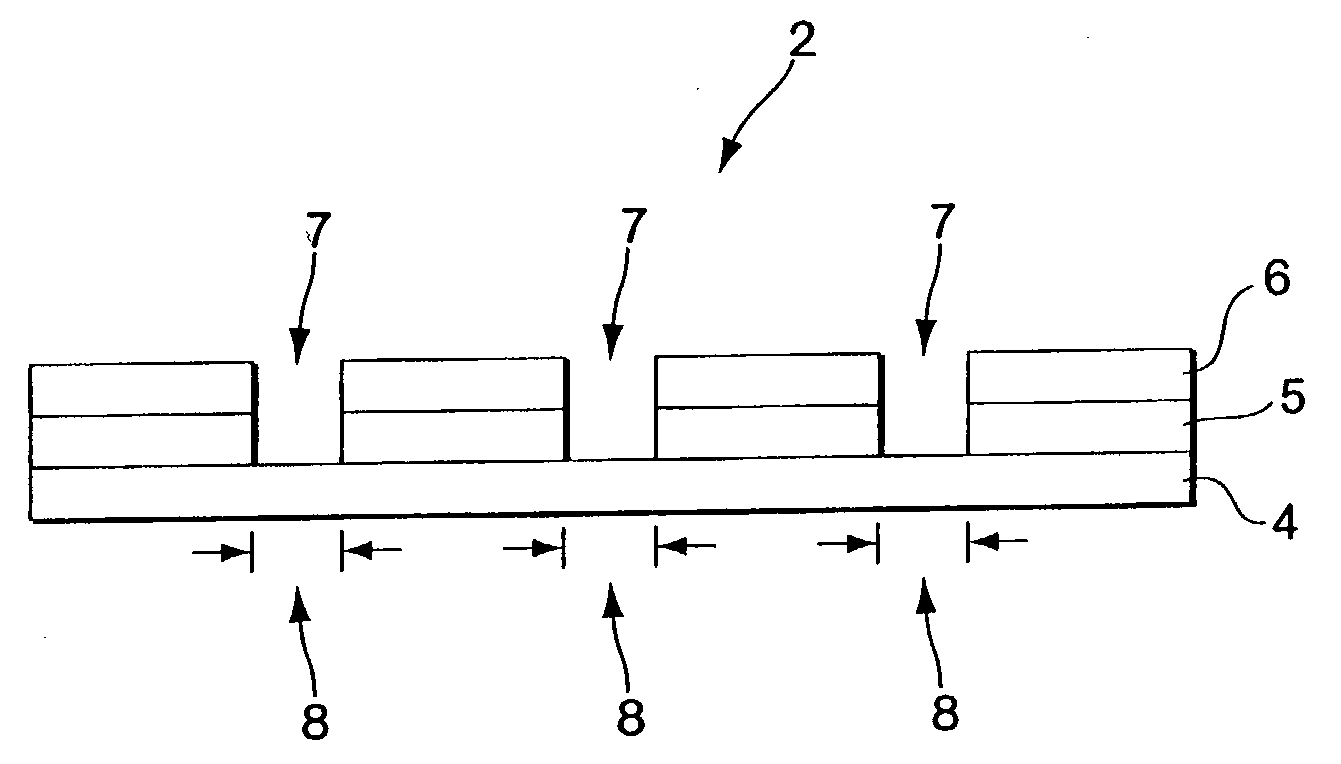
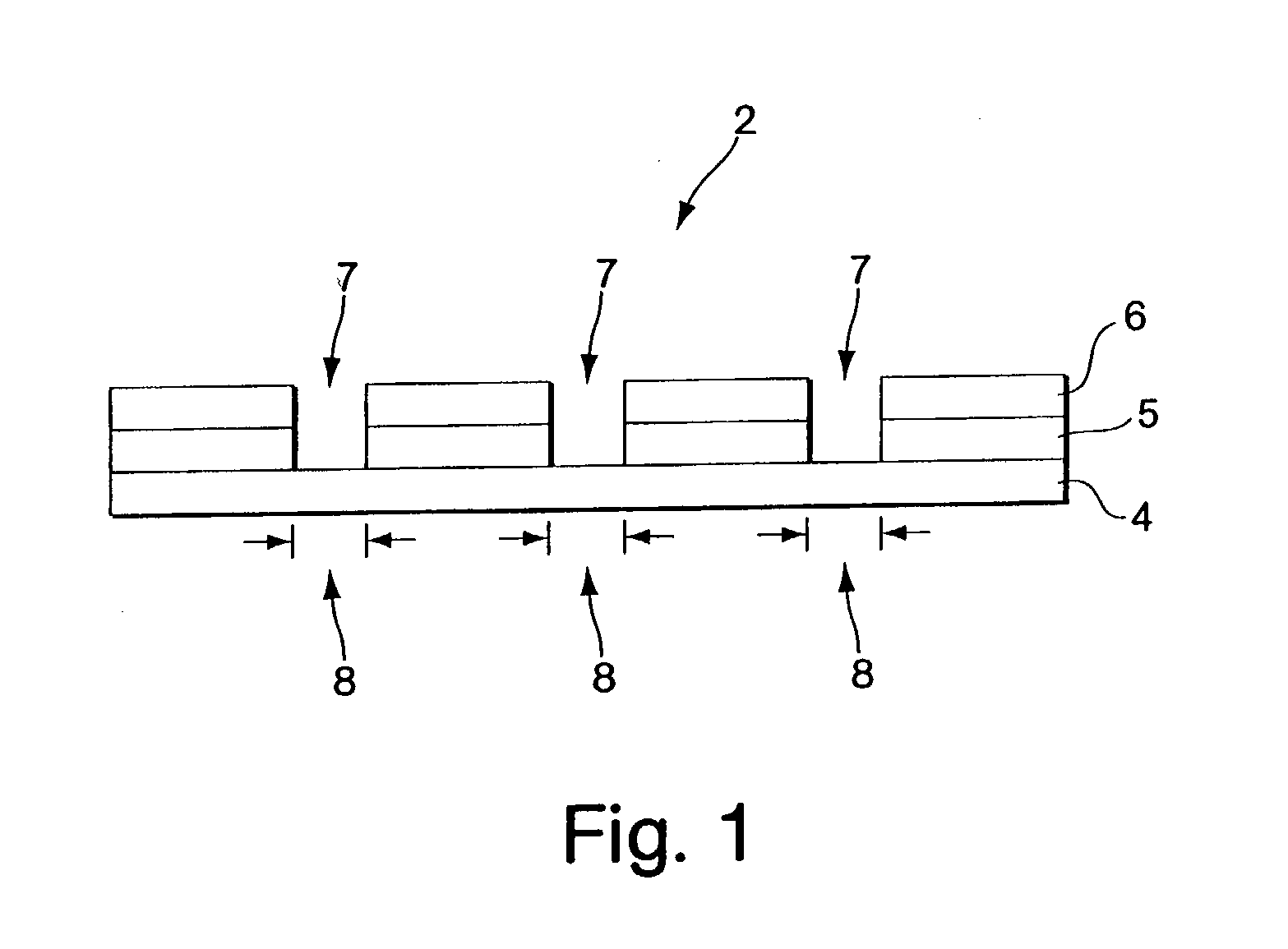
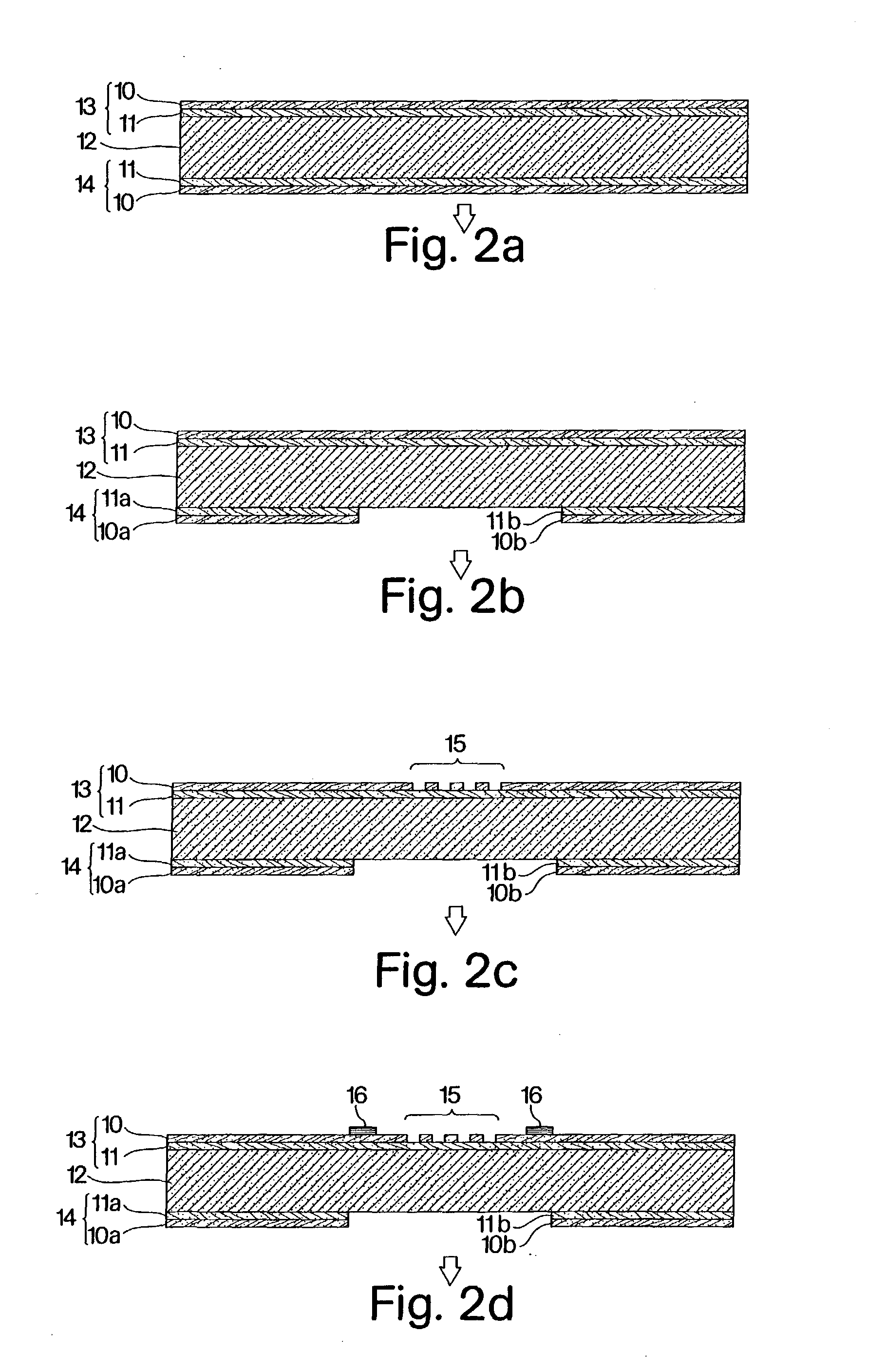
[0085] A palladium micromembrane was prepared according to the process shown in FIG. 2. In this example, the membrane included a top support layer of silicon nitride (layer thickness=0.3 .mu.m) positioned adjacent a support layer of silicon oxide (layer thickness=0.2 .mu.m). This process was developed as provided by the MEMS field. A layer of palladium (layer thickness=0.2 .mu.m) was deposited adjacent the silicon oxide layer. The holes were patterned by photolithography and have a diameter of 4 .mu.m and a total width of the device is 700 .mu.m. Only one heater segment is used in this example. The length of one heater segment is about 3.4 mm.

[0086] FIG. 8 shows a photocopy of a photograph displaying a top view of the microfabricated silicon chip incorporating the sub-micron scale membrane. Features of FIG. 8 include composite membrane 114, Pt heater 110 and perforations (holes) in SiO.sub.2 / Si.sub.3N.sub.4 112. The channel in the device is 1.2 cm long, and the...

example 2

[0088] Hydrogen Flux Through the Micromembrane

[0089] FIG. 10 shows a part of a selective flux of hydrogen from a mixture of 90 / 10 N.sub.2 / H.sub.2 at elevated membrane temperatures, using the membrane of Example 1. The devices were fixed onto an aluminum plate and mounted on an XYZ stage which contained the gas manifold and allowed for alignment with the flow card. In this experiment, a gas flow of a 9:1 mixture of nitrogen and hydrogen is contacted on one side of the membrane, and a flow of pure argon is contacted on the opposite side. The flow rates on both sides are about 20 sccm (N.sub.2 118 and H.sub.2 120). The composition of the nitrogen / hydrogen mixture exiting the device is monitored using a quadrupole massspectrometer (QMS). The membrane temperature is measured using the temperature sensing resistor on the membrane, and the membrane is heated resistively using the integrated heater and a power supply. When the membrane temperature is elevated, the exit hydrogen concentratio...

example 3

[0091] Formation of Silicon Wafer

[0092] A silicon wafer is covered with a layer of nitride, to serve as a KOH mask. The nitride on the front and back sides of the wafer is patterned, and the whole wafer is etched with 20% KOH, resulting in a capping structure shown in FIG. 12. The resulting capping wafer possesses about 250 .mu.m deep channels on one side, with an inlet and an outlet port accessing the channel from the top side, and access holes for probes etched all the way through the wafer.

[0093] The capping wafer 136 and the membrane 138 can be bonded together prior to dicing, using an adhesive layer, such as an epoxy. The bond was accomplished using a photoresist stamping method. A thin layer (.about.2 .mu.m) of photoresist was coated onto a dummy wafer. The capping wafer was briefly contacted with the photoresist, and then aligned and pressed together with the membrane wafer. The wafers were baked at 100 .degree. C. for 1 h and then the wafers were diced to release individual ...


PUM

PropertyMeasurementUnit
Angleaaaaaaaaaa
Angleaaaaaaaaaa
Angleaaaaaaaaaa

Abstract

The present invention relates to gas separation membranes including a metal-based layer having sub-micron scale thicknesses. The metal-based layer can be a palladium alloy supported by ceramic layers such as a silicon oxide layer and a silicon nitride layer. By using MEMS, a series of perforations (holes) can be patterned to allow chemical components to access both sides of the metal-based layer. Heaters and temperature sensing devices can also be patterned on the membrane. The present invention also relates to a portable power generation system at a chemical microreactor comprising the gas separation membrane. The invention is also directed to a method for fabricating a gas separation membrane. Due to the ability to make chemical microreactors of very small sizes, a series of reactors can be used in combination on a silicon surface to produce an integrated gas membrane device.

Description

RELATED APPLICATIONS[0001] This application claims the benefit of priority under 35 U.S.C. .sctn.120 of co-pending U.S. patent application Ser. No. 09 / 453,246, filed Dec. 2, 1999, which application claims the benefit of priority under 35 U.S.C. .sctn.119(e) of co-pending U.S. Provisional Patent Application Serial No. 60 / 110,687, filed Dec. 2, 1998. All of these applications are hereby incorporated by reference.FIELD OF THE INVENTION[0003] The present invention relates to separation membranes and, in particular, membranes for the purification of hydrogen. The membranes involve a metal-based layer having sub-micron scale thicknesses, and methods for the preparation of these membranes and miniature devices incorporating these membranes are disclosed. In addition, the membranes can be used to effect chemical reactions such as hydrogenation and dehydrogenation reactions.BACKGROUND OF THE INVENTION[0004] Much effort has been placed on developing synthetic membranes for applications such a...

Claims


Application Information

Patent Timeline
IPC IPC(8): B01D71/02B01D53/22B01J19/00B01J23/44C01B3/50C01B3/56H01M8/06
CPCB01D67/006Y02E60/50B01D71/022B01D2325/04B01D2325/24B01J19/0093B01J2219/00783B01J2219/00824B01J2219/00828B01J2219/00833B01J2219/00835B01J2219/00844B01J2219/00858B01J2219/0086B01J2219/00869B01J2219/00873B01J2219/00907C01B3/505C01B2203/041C01B2203/047C01B2203/0475C01B2203/0495H01M8/0612H01M8/0662B01D67/0062Y10T428/24998Y10T137/1963Y10T428/249978
Inventor FRANZ, ALEKSANDER J.JENSEN, KLAVS F.SCHMIDT, MARTIN A.FIREBAUGH, SAMARA
Owner MASSACHUSETTS INST OF TECH
Why Eureka
Try Eureka