Method and apparatus for spin-echo-train MR imaging using prescribed signal evolutions

a signal evolution and spinechotrain technology, applied in the direction of reradiation, measurement using nmr, instruments, etc., can solve the problems of not using all three of these linear gradients, introducing artifacts such as blurring, and substantially degrading image contras

Inactive Publication Date: 2004-03-18
UNIV OF VIRGINIA ALUMNI PATENTS FOUND
View PDF26 Cites 33 Cited by
  • Summary
  • Abstract
  • Description
  • Claims
  • Application Information

AI Technical Summary

Problems solved by technology

When high flip angles are used for the refocusing RF pulses, echo-train durations that are longer than these limits can substantially degrade image contrast and introduce artifacts such as blurring (See Mulkern et al.
Also, while traditional commercial methods provide linear gradients in the x, y, or z directions it is also possible not to utilize all three of these linear gradients.
In particular, the control unit commanded by its loaded software causes the generation of MR signals by controlling the application of MR pulse sequences, which comprise RF-pulses, time delays and temporary magnetic-field gradient pulses.

Method used


Image

  • Method and apparatus for spin-echo-train MR imaging using prescribed signal evolutions
  • Method and apparatus for spin-echo-train MR imaging using prescribed signal evolutions
  • Method and apparatus for spin-echo-train MR imaging using prescribed signal evolutions

Examples


example no.1

Example No. 1

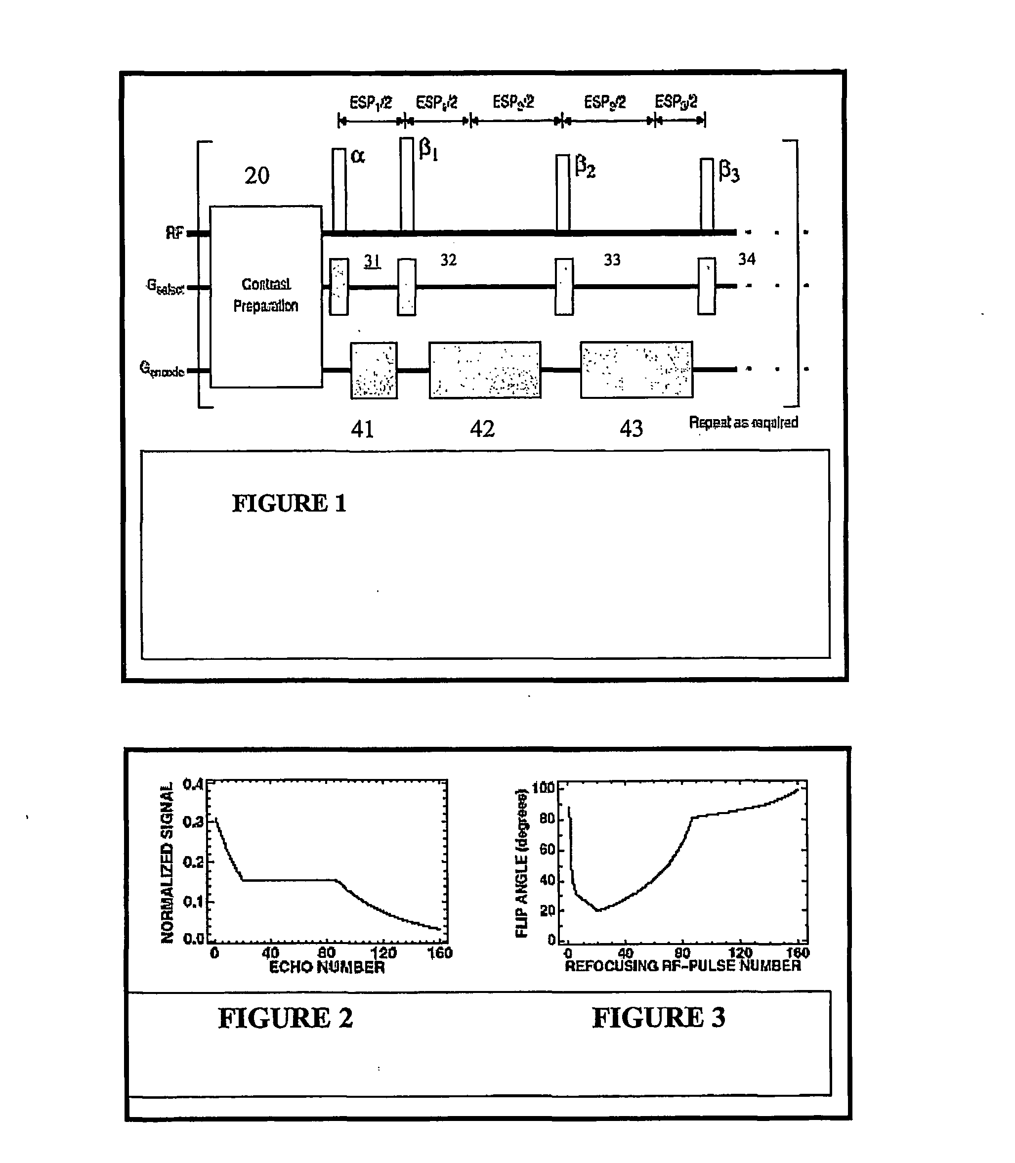
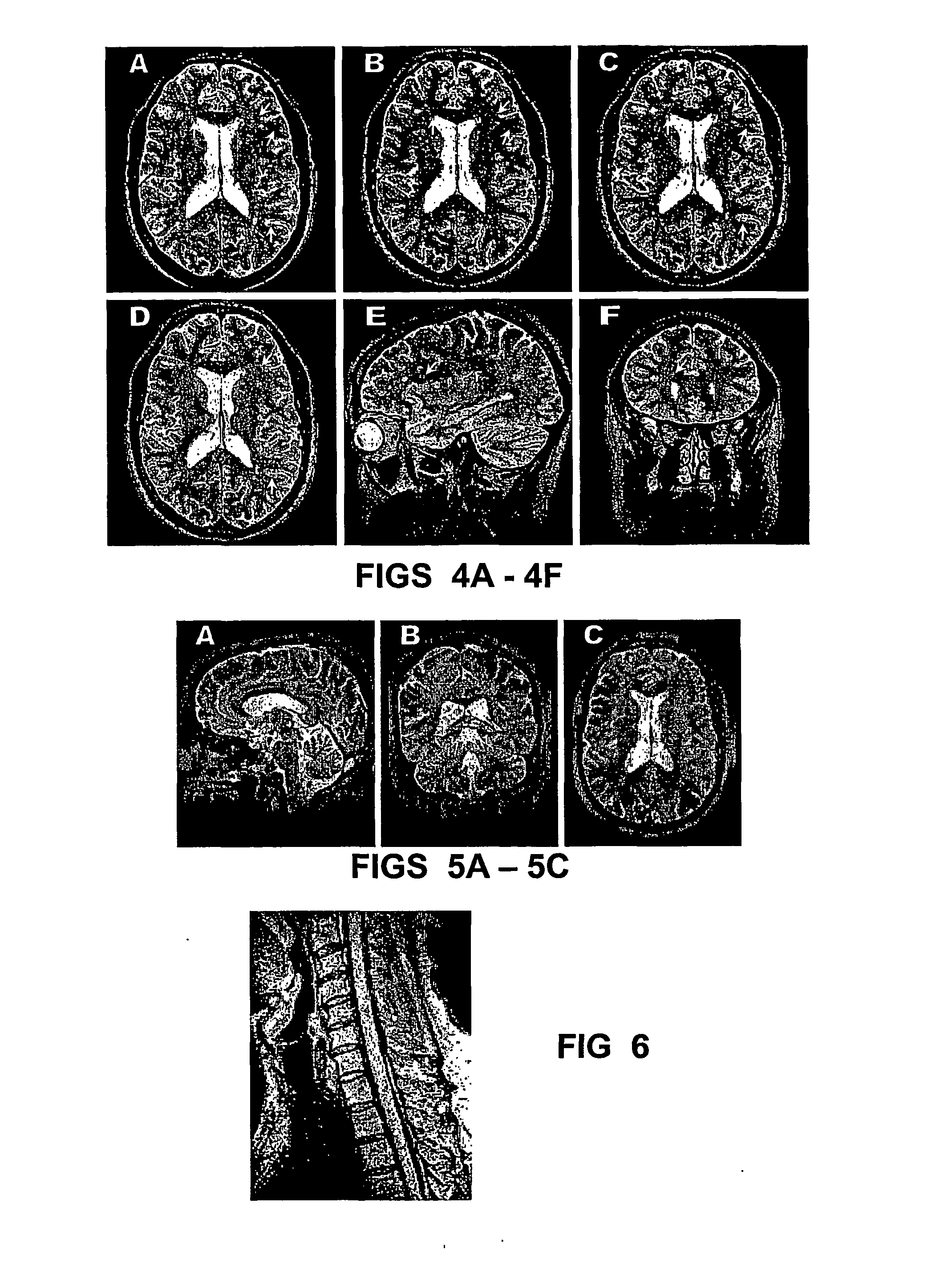
[0083] FIGS. 4B-4F show an example of MR brain images obtained at 1.5 Tesla using the variable-flip-angle series of FIG. 3 in a "turbo-SE" type spin-echo-train pulse sequence; collectively. In particular, the T2-weighted two-dimensional and three-dimensional SE images of FIGS. 4(A) and 4(B)-4(C), respectively, were obtained from a 59 year old volunteer for demonstrating age-related non-specific white-matter lesions. As can be observed, arrows mark several of these lesions. The adjacent 1-mm thick 3D images, as shown in FIGS. 4B-4D, correspond to the single 3-mm thick 2D image in FIG. 4A. In the 3D images, the phase-encoding direction corresponding to the 160-echo train is left-to-right in FIGS. 4B-4D and 4F. No image artifacts secondary to this very long spin-echo train are apparent. Pulse sequence parameters for the 10 minute 3D acquisition included the following: repetition time / effective echo time, 2750 / 328 ms; matrix, 256.times.160.times.216; field of view, 25.6.tim...

example no.2

Example No. 2

[0086] Next, referring to FIGS. 5A-5C, using the same pulse-sequence parameters as described above in FIGS. 2-4, T2-weighted images were also obtained at 3 Tesla from the brain of a healthy volunteer. The three 1-mm thick images were all reconstructed from the same 3D acquisition. These images appeared similar to those obtained at 1.5 Tesla, but exhibited higher signal-to-noise ratios. Of particular importance, the partial-body and local values for the specific absorption rate (SAR) were 1.29 W / kg and 3.16 W / kg, respectively, compared to the FDA limits for partial-body and local SAR of 3.0 and 8.0 W / kg, respectively. The SAR values at 3 Tesla were much less than the FDA limits, indicating that there remains substantial latitude in the pulse-sequence design from the perspective of power deposition, including the possibility for even more refocusing RF pulses per excitation. Thus, according to the present invention, although the use of spin-echo-train methods has been res...

example no.3

Example No. 3

[0087] Referring to FIG. 6, as the final example, FIG. 6 shows a T2-weighted sagittal image of the cervical spinal cord obtained at 1.5 Tesla from a healthy volunteer, again using a 160-echo train. The quality of cervical-spine images from T2-weighted MRI techniques is often compromised by artifacts arising from the pulsatile motion of the CSF surrounding the cord. One potential solution to this problem is to use FLAIR imaging. See Hajnal et al. While this technique can completely suppress the signal from CSF, there remains some concern about its ability to depict the full range of clinically-relevant lesions. See Hittmair et al. and Keiper et al. As illustrated in FIG. 6, an alternative is to use a T2-weighted technique with a very long spin-echo train based on a prescribed signal evolution, as provided by the present invention. The signal from CSF is uniformly suppressed without generating motion artifacts. The combination of the long echo train and the relatively low...


PUM


Abstract

A magnetic resonance imaging "MRI" method and apparatus for lengthening the usable echo-train duration and reducing the power deposition for imaging is provided. The method explicitly considers the t1 and t2 relaxation times for the tissues of interest, and permits the desired image contrast to be incorporated into the tissue signal evolutions corresponding to the long echo train. The method provides a means to shorten image acquisition times and/or increase spatial resolution for widely-used spin-echo train magnetic resonance techniques, and enables high-field imaging within the safety guidelines established by the Food and Drug Administration for power deposition in human MRI.

Description

[0001] This application claims priority from U.S. Provisional Application Serial No. 60 / 257,182, filed on Dec. 21, 2000, entitled "Spin-Echo-Train MR Imaging Using Prescribed Signal Evolutions", the entire disclosure of which is hereby incorporated by reference herein. The present application is related to U.S. Pat. No. 5,245,282, filed on Jun. 28, 1991, entitled "Three-dimensional Magnetic Resonance Imaging," the entire disclosure of which is hereby incorporated by reference herein.[0003] The present invention relates to a pulse sequence for use in operating a magnetic resonance imaging apparatus, and in particular for lengthening the usable echo-train duration and reducing the power deposition for spin-echo-train magnetic resonance imaging.BACKGROUND OF INVENTION[0004] Over the past twenty years, nuclear magnetic resonance imaging (MRI) has developed into an important modality for both clinical and basic-science imaging applications. A large portion of MRI techniques are based on ...

Claims


Application Information

Patent Timeline
Patent Type & Authority Applications(United States)
IPC IPC(8): G01R33/50G01R33/561G01R33/58
CPCG01R33/50G01R33/586G01R33/5617G01R33/5615
Inventor MUGLER III, JOHN PBROOKEMAN, JAMES R.
Owner UNIV OF VIRGINIA ALUMNI PATENTS FOUND
Why Eureka
Try Eureka