Device having a flow channel

Inactive Publication Date: 2004-04-08
ABBOTT LAB INC
View PDF11 Cites 146 Cited by
  • Summary
  • Abstract
  • Description
  • Claims
  • Application Information

AI Technical Summary

Problems solved by technology

A drawback of this device is that the cavity is filled until the aperture created by the discontinuity of the bonding and the plate is encountered.
Errors in the measurement of the concentration of an analyte in a sample of fluid occur if the dimensions of the cavity are such that the assay begins prior to the sample's reaching a state of quiescence.
Applying the mesh layer is a time-consuming step, and a biosensor employing a mesh layer may require a larger sample than does a biosensor not employing a mesh layer, primarily because a flow channel having greater dimensions may be required to insert a layer of mesh.
The use of a plurality of openings in the cover layer eliminates the problem that results from the use of a single opening that is improperly positioned with respect to the flow channel, with the result that the opening does not connect the flow channel with the external environment.
At the flow-terminating interface, the force resulting from capillary attraction is not sufficient to overcome the obstacle generated by the flow-terminating interface.
The dual-purpose reference/counter electrode still carries out its counter electrode function; however, in the case of the dual-purpose reference/counter electrode, the potential that is applied between the dual-purpose reference/counter electrode and the working electrode cannot be altered to compensate for changes in potential at the working electrode.
However, the correspondi

Method used


Image

  • Device having a flow channel
  • Device having a flow channel
  • Device having a flow channel

Examples


example 1

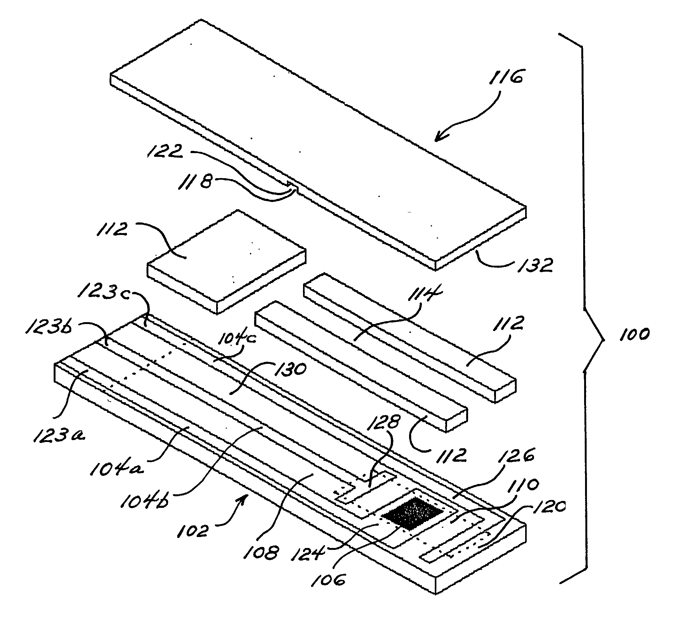
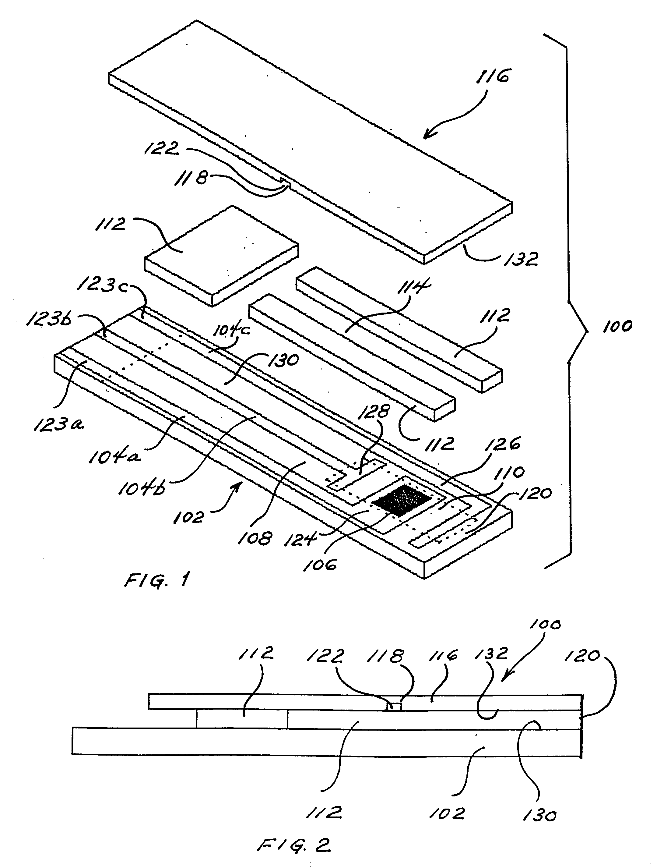
[0079] This example illustrates the preparation of a sensor strip according to this invention. The sensor strip of this example is shown in FIGS. 1 and 2.

[0080] Carbon tracks are applied to a base layer made of poly(vinyl chloride) (PVC) by means of a screen-printing technique. The carbon tracks define the position of the electrodes within the reaction site, which includes the reference electrode, counter / trigger electrode, and working electrode. The counter electrode also functions as a trigger electrode. The assay begins when the sample contacts the trigger electrode. The carbon tracks also define the position of the contacts. An insulation layer can be printed over carbon tracks to expose the defined reaction site. The insulation layer is characterized by having a portion cut therefrom to create electrical contacts that can be inserted into a meter for measuring the reaction of interest. UV-curable adhesive can be printed to form the spacer layer and define the sidewalls of the f...

example 2

[0083] In this example, the sensor strip of Example 1 is prepared, with the exception that a mixture of silver and silver chloride is printed on the track leading from the working electrode to reduce the resistance along that portion of the track.

example 3

[0084] In this example, the sensor strip of Example 2 is prepared, with the exception that a reagent layer is printed on the working electrode. This optional reaction layer comprises an enzyme, a mediator, an optional binder, and an optional filler.


PUM

PropertyMeasurementUnit
Flow rateaaaaaaaaaa
Adhesivityaaaaaaaaaa
Dimensionaaaaaaaaaa

Abstract

A device having a flow channel, wherein at least one flow-terminating interface is used to control the flow of liquid in the flow channel. The flow-terminating interface prevents the flow of the liquid beyond the interface. In one aspect, the invention provides a sensor, such as, for example, a biosensor, in the form of a strip, the sensor being suitable for electrochemical or optical measurement. The sensor comprises a base layer and a cover layer, and the base layer is separated from the cover layer by a spacer layer. The base layer, cover layer, and spacer layer define a flow channel into which a liquid sample is drawn therein and flows therethrough by means of capillary attraction. The flow of the sample is terminated by a flow-terminating interface positioned in the flow channel.

Description

[0001] This invention relates to a device for controlling the flow of a fluid in a channel where the flow results from capillary attraction. More particularly, the invention relates to a sensor for controlling the taking up of a liquid sample into the reaction site of the sensor.DISCUSSION OF THE ART[0002] Controlling the flow of fluid in a channel where the flow results from capillary attraction is important in microfluidic and microanalytical systems. The volume of fluid in an area where a chemical reaction is to be carried out often is required to be controlled to ensure precise control of the reaction or precise quantification of the analyte of interest or both.[0003] The control of the flow of a fluid may be required in order to complete a reaction step before another reaction step commences. The control of the flow of fluid may also be required to control the effects of dilution. The control of the flow of fluid may also be required to maintain the flow after the completion of...

Claims


Application Information

Patent Timeline
IPC IPC(8): B01L3/00C12Q1/00G01N27/403G01N33/487
CPCB01L3/502723B01L2300/0645B01L2300/0825G01N27/3272B01L2400/0688C12Q1/001B01L2400/0406
Inventor KARINKA, SHRIDHARA ALVATESS, MARK E.
Owner ABBOTT LAB INC
Why Eureka
Try Eureka