Laser irradiation apparatus and method of manufacturing semiconductor device by using the laser irradiation apparatus
a laser irradiation and laser beam technology, applied in metal working apparatus, manufacturing tools, transistors, etc., can solve the problems of inferior heat resistance of glass substrates and inability to uniformly irradiate semiconductor films with laser beams
- Summary
- Abstract
- Description
- Claims
- Application Information
AI Technical Summary
Benefits of technology
Problems solved by technology
Method used
Image
Examples
embodiment 1
[0045] Embodiment 1
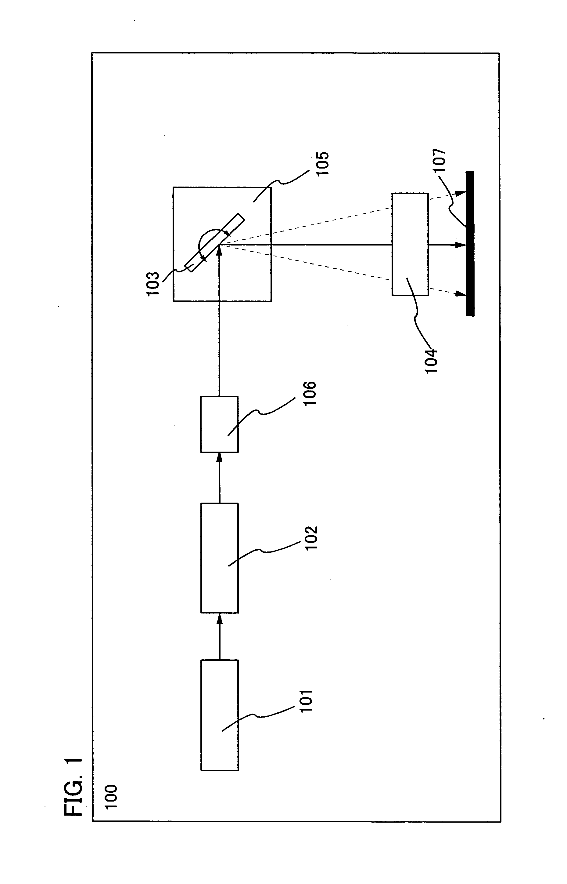
[0046] This embodiment describes a structure in which a half-wave plate and a beam splitter are interposed between an optical system for shaping a beam and a galvanometer mirror.
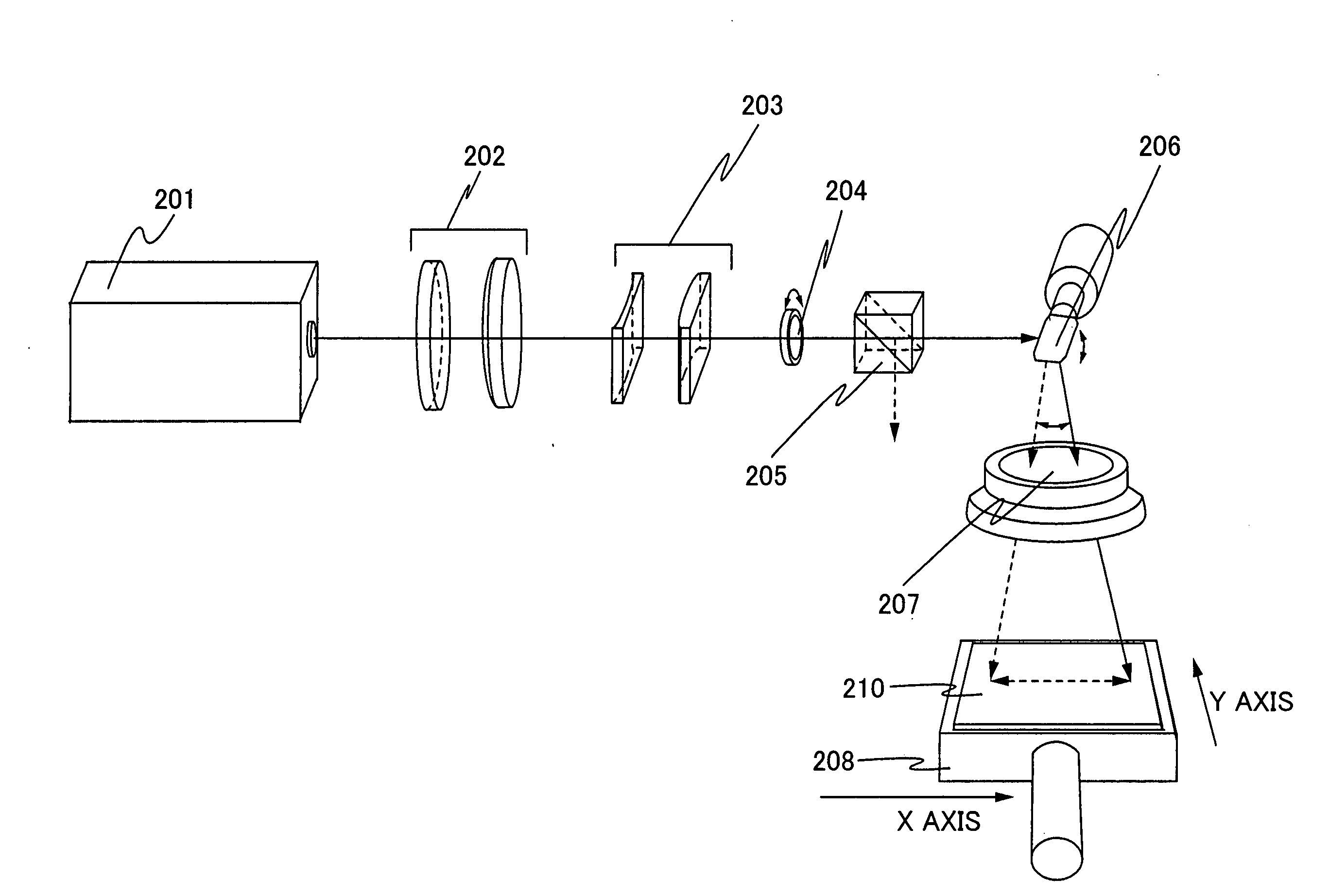
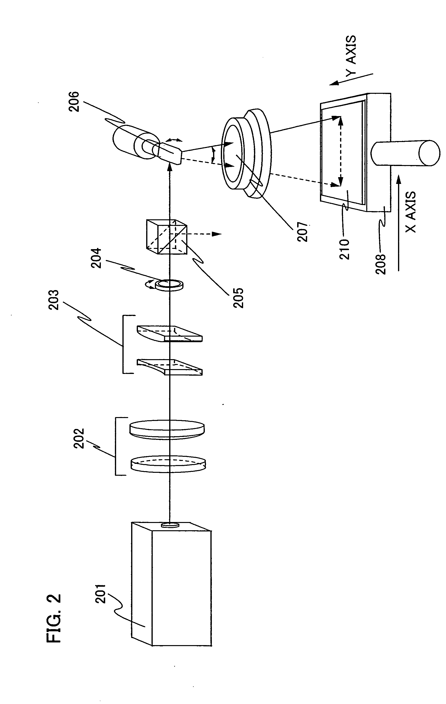
[0047] FIG. 2 shows an example of a laser irradiation apparatus. The description given here is about a case in which a laser beam emitted from a laser oscillator 201 is linearly p-polarized light beam (light beam is hereinafter referred to as beam) according to the polarization characteristic of the laser. A laser beam emitted from the laser oscillator 201 is shaped into a linear beam by a beam expander 202 and a cylindrical lens 203.
[0048] The shaped beam enters a half-wave plate 204. The half-wave plate 204 rotates about the normal line that runs in the center of the incident plane, thereby changing the branching ratio of polarization of the laser beam. In this way, the ratio of p-polarized laser beam in transmitted beam from the half-wave plate 204 can be increased or decreased.
[0049] T...
embodiment 2
[0056] Embodiment 2
[0057] The case in which the scanning of the laser beam shown in the embodiment 1 is performed by controlling a galvanometer mirror in both X axis and Y axis directions is described in this embodiment.
[0058] The energy of the laser beam scanned depending on the change of a transmittance is changed, since the transmittance of the f-.theta. lens in the apparatus changed by location. FIGS. 6A and 6B shows an example of an irradiation energy change of the laser beam scanned on a substrate. FIGS. 6A and 6B shows that laser intensity around the center of a substrate is high, while the laser intensity becomes lower concentrically from the center toward edges of the substrate. Accordingly, around the center of the substrate in which the transmittance of the lens is high, the irradiation energy change on the substrate can be suppressed by controlling the rotation of a half-wave plate so that intensity of the beam transmitted from a beam splitter can be reduced.
[0059] FIGS....
embodiment 3
[0062] Embodiment 3
[0063] This embodiment describes a structure in which the half-wave plate is interposed between the optical system for shaping a beam and the galvanometer mirror.
[0064] A case in which a laser beam emitted from a laser oscillator is linearly polarized is described. Given here as an example is a case of using a laser whose polarization characteristics cause p-polarization.
[0065] A laser beam emitted from the laser oscillator is shaped by an optical system. The shaped beam enters the half-wave plate. The half-wave plate rotates around the axis that is the normal line of the half-wave plate, thereby changing the branching ratio of polarization of the incident beam. In this way, the ratio of p-polarized beam in incident beam can be increased or decreased. When the laser beam enters the half-wave plate in a manner that positions the oscillation direction of the incident beam in parallel to the optical axis direction of the half-wave plate, the laser beam, which is p-po...
PUM
| Property | Measurement | Unit |
|---|---|---|
| Ratio | aaaaa | aaaaa |
| Transmittivity | aaaaa | aaaaa |
| Reflectance | aaaaa | aaaaa |
Abstract
Description
Claims
Application Information
 - R&D
- Intellectual Property
- Life Sciences
- Materials
- Tech Scout
- Unparalleled Data Quality
- Higher Quality Content
- 60% Fewer Hallucinations
Browse by: Latest US Patents, China's latest patents, Technical Efficacy Thesaurus, Application Domain, Technology Topic, Popular Technical Reports.
© 2025 PatSnap. All rights reserved.Legal|Privacy policy|Modern Slavery Act Transparency Statement|Sitemap|About US| Contact US: help@patsnap.com


