Real-time polishing pad stiffness control using magnetically controllable fluid

a magnetic control and polishing pad technology, applied in the direction of carpet cleaners, instruments, photosensitive materials, etc., can solve the problems of non-uniform thickness and removal rate within water, and achieve the effect of reducing the difficulty of wiwnu and controlling the removal rate in specific areas of the wafer

Inactive Publication Date: 2004-04-22
TEXAS INSTR INC
View PDF6 Cites 26 Cited by
  • Summary
  • Abstract
  • Description
  • Claims
  • Application Information

AI Technical Summary

Benefits of technology

0008] In accordance with another embodiment of the present invention an improved CMP polishing apparatus is providing including a platen / table and a polishing pad on the platen / table; a polishing head for holding an object to be polished and providing pressure of the wafer against the polishing pad on the platen / table. A sub-pad between the polishing pad and the platen / table for providing mechanical support under the polishing pad. The sub-pad contains regions or pockets of magnetorheological fluid about the pad for controlling the stiffness in real time control. A magnetic field generator applies a selective magnetic field to selective regions or pockets of magnetorheological fluid in the sub-pad to control the stiffness of the sub-pad to provide real time control of the polishing of regions of the object being polished.

Problems solved by technology

Differences in Chemical Mechanical Polishing (CMP) pressure and polish pad properties result in removal rate and thickness non-uniformities within-water (WIWNU).
Control of removal rate in specific areas on the wafer is currently very difficult, requiring multi-chamber pressure control to different parts of the wafer.

Method used


Image

  • Real-time polishing pad stiffness control using magnetically controllable fluid
  • Real-time polishing pad stiffness control using magnetically controllable fluid
  • Real-time polishing pad stiffness control using magnetically controllable fluid

Examples


Embodiment Construction

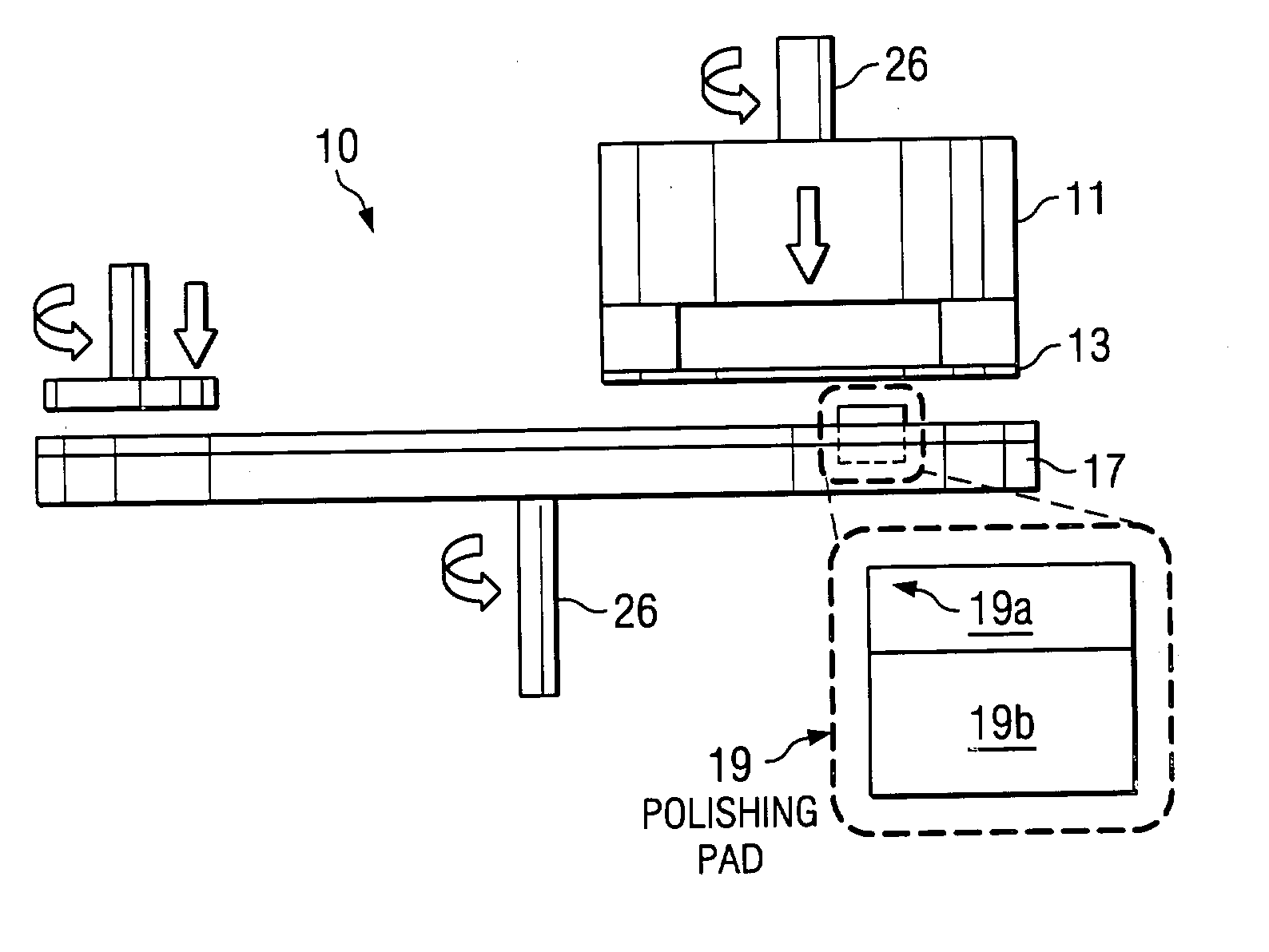
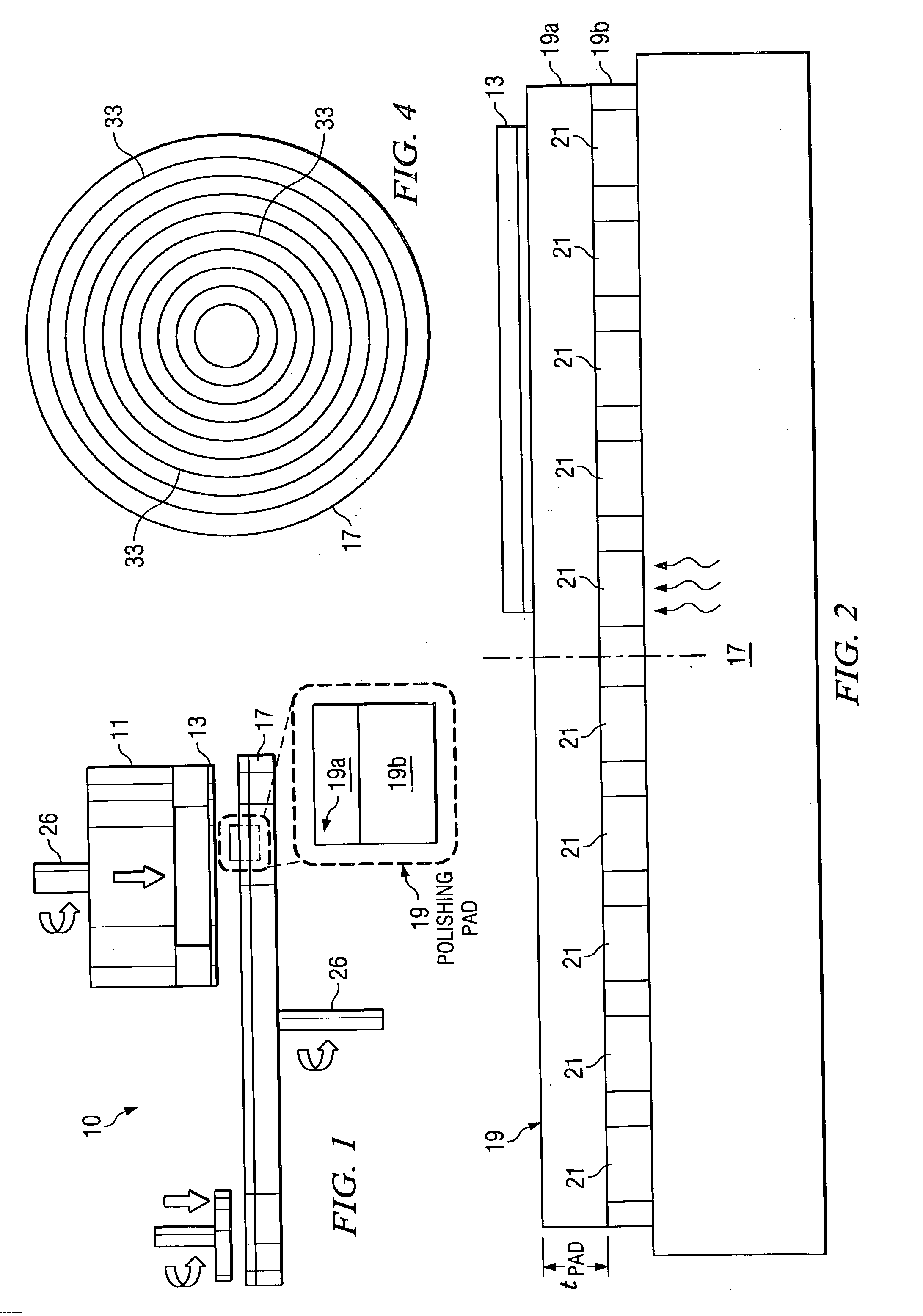
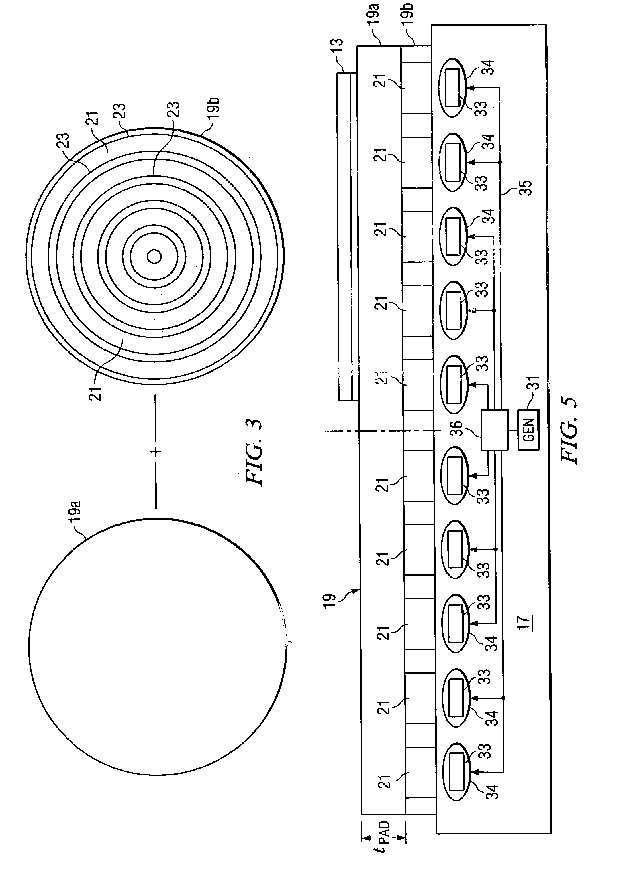
[0017] FIG. 1 illustrates for example a Copper (Cu) CMP polishing hardware 10. In accordance with one embodiment of the present invention an AMAT Mirra CMP polisher 10 is used as illustrated in FIG. 1. The set up comprises a polish head 11 that holds wafer 13 and provides the downward rotating force onto the polishing pad 19. The polishing pad 19 is mounted on a rotating platen or table 17.

[0018] The pad 19 comprises a top polishing pad 19a and a sub-pad 19b under top pad 19a for mechanical support. The top polishing pad 19a is a porous polishing pad. The top pad 19a is for example an open cell of foamed polyurethane or a sheet of polyurethane with a concentric circle grooved surface with asperity surface that aids mechanical polishing action and slurry distribution. The top pad 19a material is wetted with a polishing slurry of mostly de-ionized water and some abrasive including, but not limited to aluminum oxide, silicon dioxide, cerium oxide, zirconium oxide, or these particles co...


PUM

PropertyMeasurementUnit
pressureaaaaaaaaaa
magnetic fieldaaaaaaaaaa
stiffnessaaaaaaaaaa

Abstract

A method of CMP polishing of a semiconductor wafer is described that includes using a polishing pad on a platen/table with the polishing pad including a sub-pad containing pockets of magnetorheological fluid. The stiffness of the sub-pad is controlled by selectively applying a magnetic field at selective pockets containing magnetorheological fluid to change the viscosity of the magnetorheological fluid. The changing stiffness increases the polishing rate of the pad in the areas of the magnetic field.

Description

[0001] This invention relates to semiconductor processing and more particularly to chemical mechanical planarization (CMP) using polishing pad stiffness control with magnetically controllable fluid that causes a rheology change (a magnetorheological fluid).BACKGROUND OF INVENTION[0002] In semiconductor device fabrication, silicon wafers, after undergoing a pattern, deposition, etching, etc. process to form electrical devices and circuits on a layer there is coated a layer of glass or oxide that is polished. In the case of adding another layer of devices and circuits an interconnect between layers is provided by forming a hole in the layer of glass or dielectric and filling the hole with copper and polishing off the copper. Chemical-mechanical polishing (CMP) is widely used as a process for achieving global planarization in semiconductor manufacturing. The pattern on the wafers below the top surface makes the polishing rate non-linear. The hills and valleys resulting from the product...

Claims


Application Information

Patent Timeline
Patent Type & Authority Applications(United States)
IPC IPC(8): B24B1/00B24B37/26H01L21/321
CPCB24B1/005H01L21/3212B24B37/26
Inventor KIM, ANDREW TAEBORST, CHRISTOPHER L.LOSEY, MATTHEW W.
Owner TEXAS INSTR INC
Why Eureka
Try Eureka