System and cartridge for processing a biological sample

a biological sample and system technology, applied in the field of system and cartridge for processing a biological sample, can solve the problems of preventing the obtaining of reliable tests, cross-contamination of liquid samples, and difficulty for laboratory researchers

Inactive Publication Date: 2004-07-22
COMBIMATRIX CORP
View PDF32 Cites 71 Cited by
  • Summary
  • Abstract
  • Description
  • Claims
  • Application Information

AI Technical Summary

Benefits of technology

[0008] A main aim of the invention is therefore to provide a sample processing system and a cartridge that makes possible to avoid at least one of the above-mentioned drawbacks, and preferably all of them.
[0042] The main advantage of the inventive sample processing system and the inventive cartridge is that they make possible to achieve a bubble-free filling of the process chamber with the liquid sample to be examined, thereby ensuring that the entire active surface of the microarray device is contacted by said liquid. Moreover, the possible contamination of the liquid sample to be examined by carryover is eliminated, because the cartridge (which receives the liquid sample to be examined) is only connected to the end part of a pipettor during the short time intervals wherein the liquid sample is introduced into the cartridge. The risk of contamination by carry-over is eliminated in particular by using disposable pipetting tips for effecting the pipetting operations. Also the other above mentioned drawbacks of the above-mentioned prior art apparatuses, such as clogging of valves or conduits and use of expensive valve blocks, is eliminated by the sample processing system and cartridge according to the invention. Therefore, the present invention provides a sample processing system and cartridge that makes possible to obtain reliable test results and to achieve a substantially reliability of operation.

Problems solved by technology

While this process is relatively simple, it is labor-intensive and requires an operator to be present for 6-10 steps over a 16-24 hour period of time.
That is often difficult for laboratory researchers whom do not frequently remain at laboratories for an entire 24 hour day.
On the one hand, air bubbles in the valve block and / or the connecting conduit that get into the process chamber prevent the entire active surface of the chip from being accessible to the liquid sample to be examined, and thereby prevent obtaining reliable test results.
However, either the use of one and the same valve block over longer periods of time, connection of the same valve block to different process chambers or the lack of a valve block altogether, raises the problem of cross-contamination by carry-over of the liquid samples to be tested.
Additional problems encountered, including clogging of the valves that can arise due to high salt concentration of liquids being processed, are a further drawback that negatively affects the reliability of the operation of the analysis system.
Moreover when several cartridges are processed in parallel, a plurality of conduits and a complex and therefore expensive valve block is required in order to supply the liquid samples to be tested to the cartridges.

Method used


Image

  • System and cartridge for processing a biological sample
  • System and cartridge for processing a biological sample
  • System and cartridge for processing a biological sample

Examples


example 2

Of A System According To The Invention

[0086] A preferred embodiment of a sample processing system according to the invention is shown by FIG. 10. This system comprises a cartridge 12 of the above-described type and an optical scanning means 51 for performing a two-dimensional optical measurement of the active surface 17 of the microarray device 16. Preferably, fluorescent or chemiluminescent illumination is scanned.

[0087] A preferred embodiment of the optical means 51 for fluorescent detection comprise a light source 52, first light filter means 53, a light receiving element 54, and second light filter means 55.

[0088] Light source 52 serves for irradiating active surface 17 of microarray device 16 with excitation light necessary e.g. for fluorescence measurements.

[0089] First light filter means 53 are arranged between light source 52 and active surface 17 located within cartridge 12. First light filter means 53 serve for irradiating active surface 17 with light having a wave length ...

example 3

Of A System According To The Invention

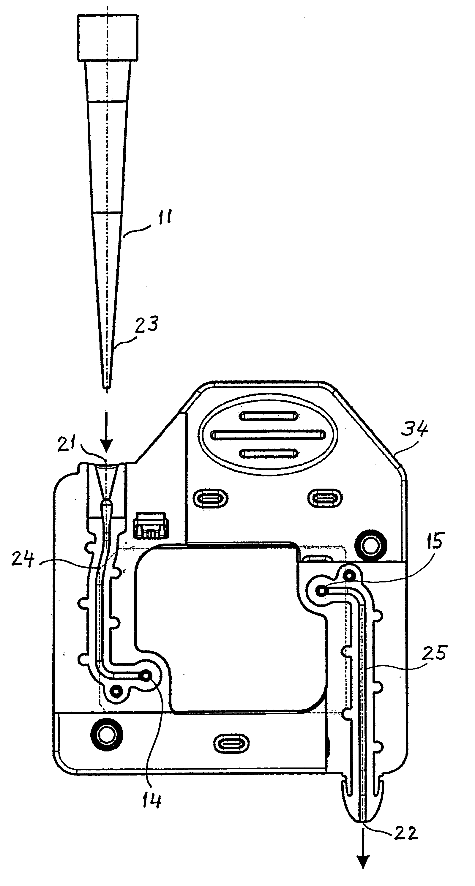
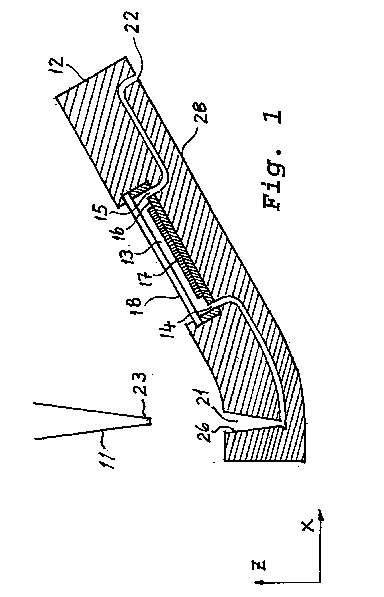
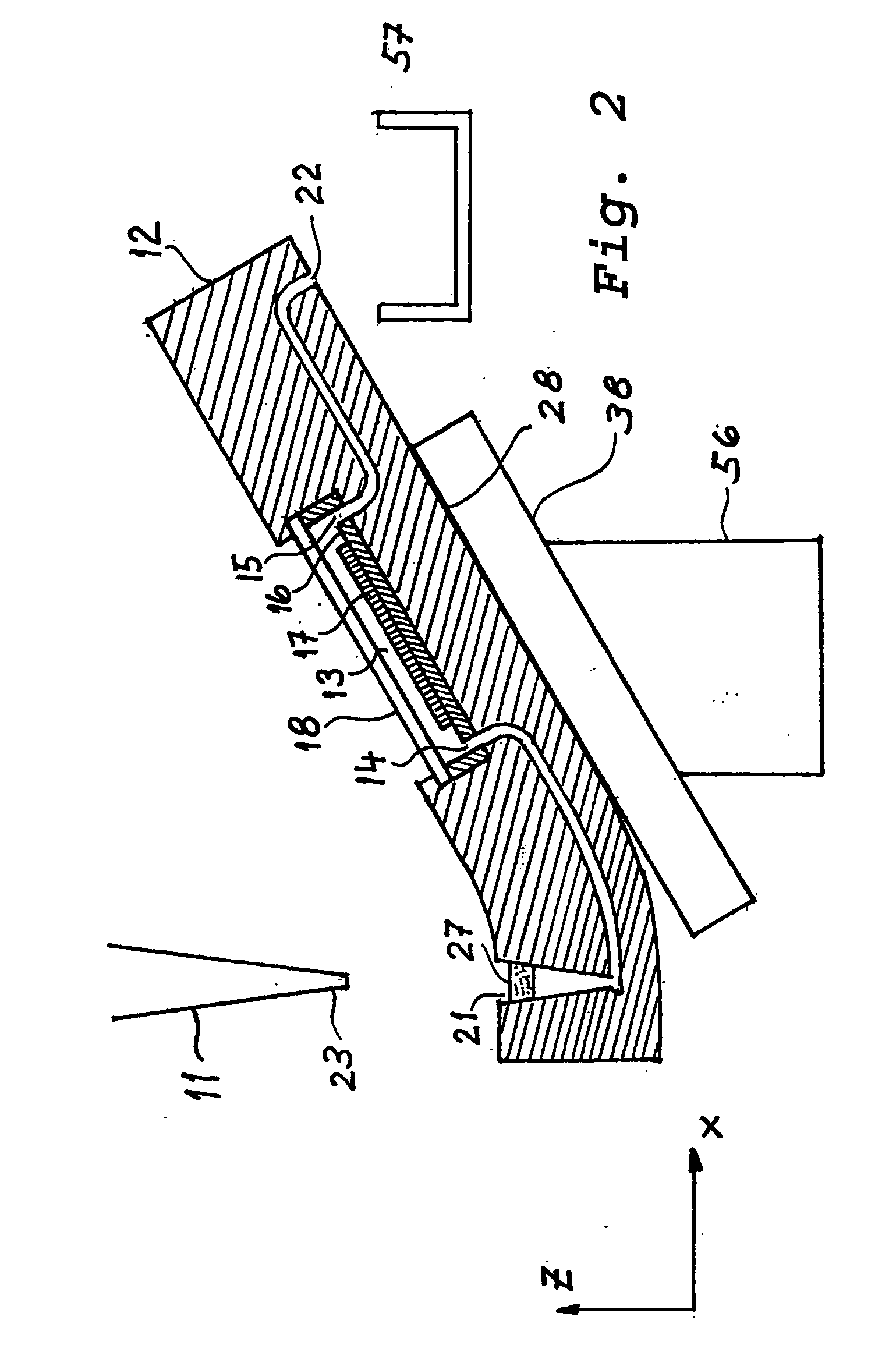
[0094] A preferred embodiment of a system according to the invention is shown by FIG. 2. This system comprises a cartridge 12 having the above-described features, a cartridge holder 56 and a waste container 57 for receiving excess liquid flowing out of the flow-cell outlet 15.

[0095] Cartridge holder 56 is adapted for holding cartridge 12 in such a position that the flow-cell inlet 14 lies at a lower height than the flow-cell outlet 15, so that liquid supplied to the flow-cell chamber 13 through inlet 14 displaces air contained in chamber 13 and enables a complete and bubble free filling of chamber with liquid, any excess of liquid leaving chamber 13 through flow-cell outlet 15.

[0096] In a preferred embodiment, the amount of liquid supplied to the flow-cell chamber 13 is larger than the volume of the flow-cell chamber, so that excess liquid flows out of flow-cell outlet 15 and is collected by waste container 57.

[0097] In another preferred embodim...

example 4

Of A System According To The Invention

[0107] A preferred embodiment of a system according to the invention comprises a plurality of cartridges 12 having the above-described features, a cartridge holder 56 for holding a plurality of cartridges 12, and a waste container 57 for receiving excess liquid flowing out from any and all of the outlet ports 22 of a plurality of cartridges 12.


PUM

PropertyMeasurementUnit
depthaaaaaaaaaa
depthaaaaaaaaaa
thicknessaaaaaaaaaa

Abstract

There is disclosed a sample processing system for processing a sample contained in a liquid. Specifically, there is disclosed a sample processing system comprising a pipettor, and a cartridge. The cartridge comprises a chamber which has an inlet and an outlet. The chamber contains a microarray device having an active surface. The active surface is accessible to liquid contained in the chamber. The cartridge further comprises an optical interface that provides optical access to the active surface of the microarray device, an inlet port and an outlet port. The inlet port is so configured and dimensioned that it forms an air-tight connection with a pipette tip when the pipette tip is inserted into the inlet port.

Description

[0001] The present invention relates to a system for processing a biological sample contained in a liquid. The invention further relates to a cartridge holder of a microarray device useful for processing a biological sample contained in a liquid. More specifically, the invention relates to a cartridge holder of a microarray device designed for an automatic pipetting system for automatically dispensing liquids to communicate with the microarray device.DESCRIPTION OF RELATED ART[0002] Within the context of the instant invention is a chip or microarray-shaped carrier is a substrate, in particular a glass or silicon chip diced from a wafer and printed as a semiconductor device. The chip or microarray device can be of any shape when cut out of a wafer, but such devices are best packed onto a wafer format in a square or rectangular shape. A printed wafer generally has a thickness of about 0.7 to about 1.0 millimeter. The microarray semiconductor device has a printed face or "active surfac...

Claims


Application Information

Patent Timeline
Patent Type & Authority Applications(United States)
IPC IPC(8): G01N21/64B01J4/02B01L3/00B01L9/00C40B40/06C40B60/14G01N21/05G01N21/76G01N21/78G01N33/53G01N35/00G01N35/02G01N35/08G01N35/10G01N37/00
CPCB01J2219/00286G01N2035/00158B01J2219/00495B01J2219/00529B01J2219/00585B01J2219/00596B01J2219/00608B01J2219/00612B01J2219/00659B01J2219/00722B01L3/502715B01L3/502723B01L9/527B01L2200/027B01L2200/10B01L2200/14B01L2300/0636B01L2300/0654B01L2300/0816B01L2300/0877B01L2300/1805B01L2400/0487C40B40/06C40B60/14G01N35/00029G01N35/10B01J2219/00364
Inventor HANDLER, ERICHDEGENHARDT, VOLKERPROKOP, SARA AKIKOSLOTA, MICHAEL WILLIAM
Owner COMBIMATRIX CORP
Why Eureka
Try Eureka