Method of Forming Fluorescent Surface and Image Display Unit

a technology of fluorescent surface and image display unit, which is applied in the field of forming phosphor screens, can solve the problems of poor film forming property of metal back layer thereon, deformation of withstand pressure characteristic of phosphor screens, and cracks in metal back layers, so as to improve the density of phosphor layers, improve the withstand voltage characteristic, and improve the effect of metal back effects

Inactive Publication Date: 2004-08-05
KK TOSHIBA
View PDF3 Cites 7 Cited by
  • Summary
  • Abstract
  • Description
  • Claims
  • Application Information

AI Technical Summary

Benefits of technology

[0013] According to the present invention, a metal back layer (metal film) free from cracks, pinholes or the like and having good characteristics is formed, and a phosphor screen having a high metal back effect and a substantially improved withstand voltage characteristic is obtained. And, the phosphor screen is improved its emission brightness because denseness of the phosphor layer is improved.
[0023] The structure of the phosphor screen obtained as described above is shown sectionally in FIGS. 1A, 1B (FIG. 1A being a magnified diagram). As shown in FIG. 1A, the surface of a phosphor layer 1 is smoothed, the surface roughness is reduced to remedy unevenness, and a difference in level of the phosphor layer 1 of individual colors is reduced as shown in FIG. 1B. And, denseness (packed degree) of phosphor particles 1a in the phosphor layer 1 is also improved by such forced pressurizing. In the drawing, reference numeral 2 denotes a glass substrate, and 3 denotes a light absorption layer.
[0027] Thus, the metal back layer which is free from cracks, pinholes or the like and has remarkable characteristics is formed, and the phosphor screen having high metal back effects and a significantly improved withstand voltage characteristic can be obtained. Besides, denseness of the phosphor layer is improved, so that emission brightness of the phosphor screen is improved. And, by forming the phosphor screen on the inner surface of the face plate by such a method, an image display unit, which has a high effect of the metal back layer and a good withstand voltage characteristic and can make highly bright and high quality display, is obtained.

Problems solved by technology

The phosphor screen formed by a conventional method, however, had a phosphor layer 21 with large surface roughness (unevenness) as shown in a magnified form in FIG. 3A and also had largely different levels due to a difference in thickness of the phosphor layers 21 having individual colors as shown in FIG. 3B, so that a film forming property of a metal back layer thereon was poor, and the metal back layer had cracks, pinholes and the like.
And, there was a disadvantage that a withstand pressure characteristic of the phosphor screen was degraded because of cracks, wrinkles, pinholes and the like of the metal back layer.
It was also difficult to obtain a phosphor screen having high brightness, and particularly a display unit such as an FED operating in a low-speed electron beam area had inconsistencies in brightness.

Method used


Image

  • Method of Forming Fluorescent Surface and Image Display Unit
  • Method of Forming Fluorescent Surface and Image Display Unit
  • Method of Forming Fluorescent Surface and Image Display Unit

Examples


example 2

[0039] First, a blue phosphor paste, a green phosphor paste and a red phosphor paste having the following compositions were prepared.

4 [Blue phosphor paste] Butyl carbitol acetate 50.0 parts Blue phosphor material (ZnS:Ag, Cl) 4.0 parts Ethyl cellulose 46.0 parts

[0040]

5 [Green phosphor paste] Butyl carbitol acetate 50.0 parts Green phosphor material (ZnS:Cu, Al) 4.0 parts Ethyl cellulose 46.0 parts

[0041]

6 [Red phosphor paste] Butyl carbitol acetate 50.0 parts Red phosphor material (Y.sub.2O.sub.2S:Eu) 4.0 parts Ethyl cellulose 46.0 parts

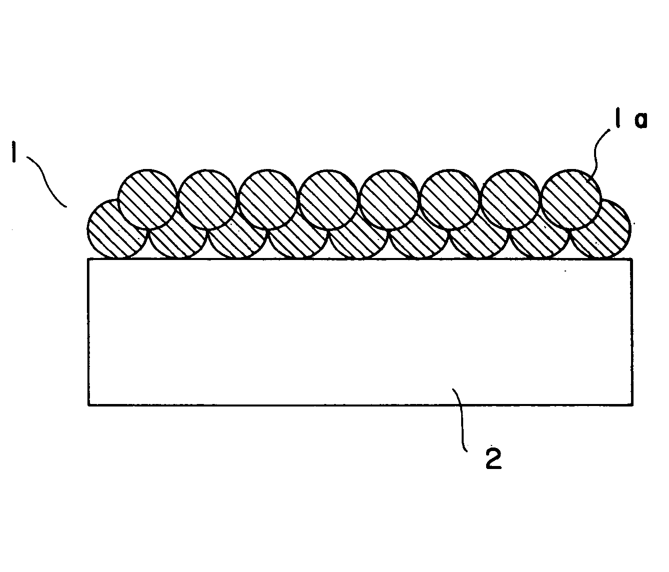
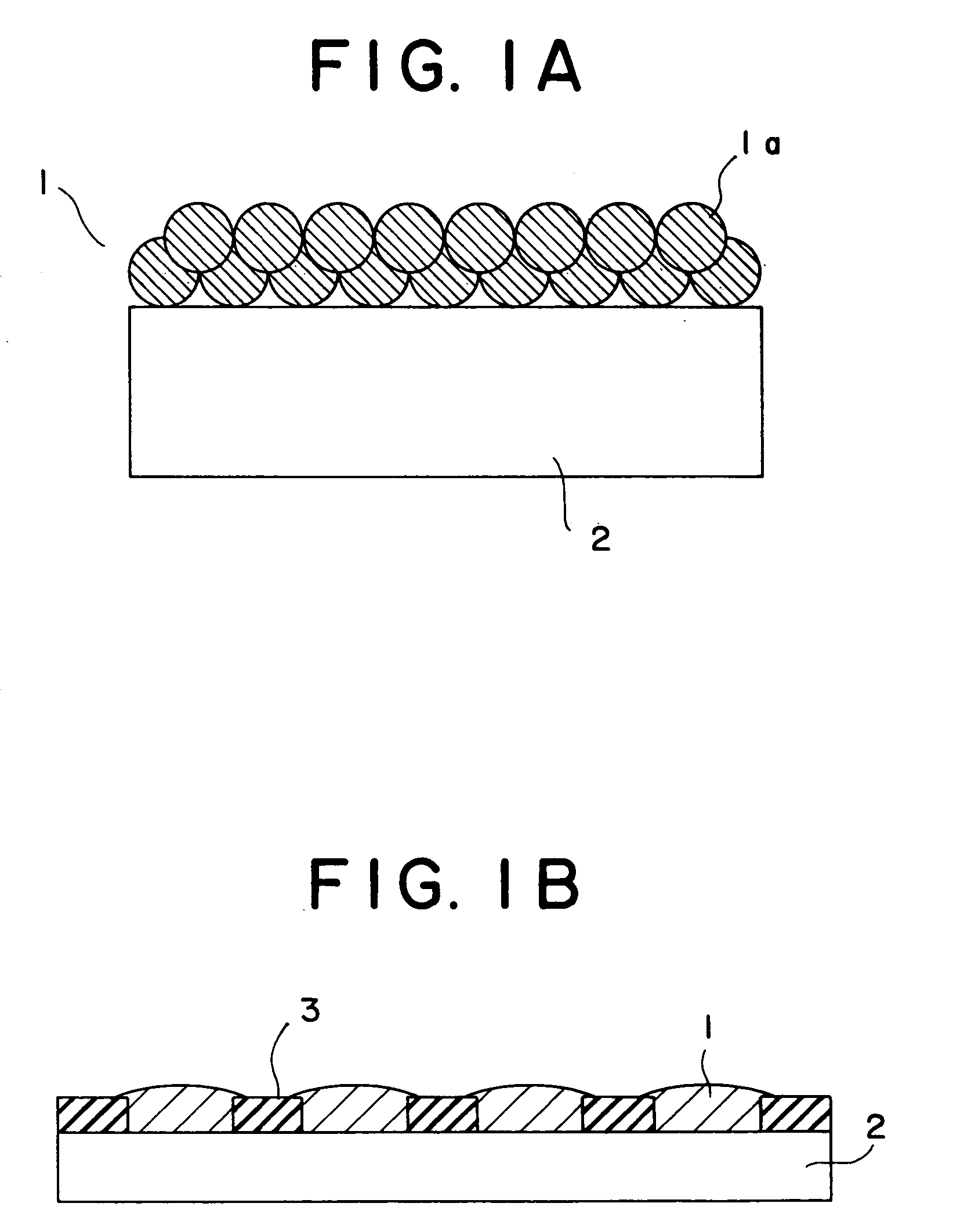
[0042] Then, the above-described phosphor pastes of the individual colors were applied to a glass substrate, on which a striped light absorption layer (BM) of a black pigment was previously formed at a prescribed position, by a screen printing method and dried so to form the phosphor layer of individual colors of red (R), green (G) and blue (B) into a stripe pattern.

[0043] Next, the phosphor screen having the light absorption layer and the phosphor l...

example 3

[0047] The phosphor screen formed by Example 2 was pressurized under 980 N / cm.sup.2 by a roller at a speed of 1 m / min while heating to 150.degree. C., and a metal back layer was formed on the phosphor screen by a transfer method.

[0048] Specifically, the transfer film, in which the Al film was superposed on the base film of polyester resin or the like through a parting agent layer, the adhesive agent layer being formed thereon, was disposed on the phosphor screen so to contact the adhesive agent layer with the phosphor screen undergone the heating / pressurizing treatment and pressed by a heating roller for intimate adhesion, then the base film was peeled to adhere the Al film onto the phosphor screen.

[0049] Then, the phosphor screen to which the Al film was transferred was heated for baking at 450.degree. C. for 30 minutes to decompose / remove the organic contents, and the Al film was examined for evaluation of the presence or not of cracks and pinholes.

[0050] As Comparative Example 3,...


PUM

PropertyMeasurementUnit
softening temperatureaaaaaaaaaa
pressureaaaaaaaaaa
temperatureaaaaaaaaaa

Abstract

A method for forming a phosphor screen comprising the step of forming a phosphor layer containing a thermoplastic resin on the inner surface of a face plate, the step of pressurizing the phosphor layer being heated to plasticate the thermoplastic resin and smooth the surface of the phosphor layer, and the step of forming a metal film on the surface-smoothed phosphor layer and heating the face plate. Thermoplastic resin having a softening temperature of 50-350° C. can be used in the phosphor layer, and 0.05-50 wt % of such a thermoplastic resin in solid content ratio is contained in the layer. Heating / pressurizing conditions preferably involve temperatures of 50-350° C. and pressures of 10-10000 N / cm<2>. This method enhances the film forming property of a metal back layer and prevents cracks and pinholes in the metal back layer.

Description

[0001] The present invention relates to a method for forming a phosphor screen and an image display unit having the phosphor screen.[0002] For a conventional image display unit such as a cathode-ray tube (CRT) or a field emission display (FED), a metal back-attached phosphor screen, which has a metal film of aluminum (Al) or the like formed on the inner surface (surface opposite to the face plate) of a phosphor layer, has been used extensively.[0003] Such a metal film is called the metal back layer and it reflects light advancing to an electronic source, which is in light emitted from a phosphor material by electrons emitted from the electronic source, toward the face plate to enhance brightness and also serves to stabilize the potential of the phosphor layer as an anode electrode. And, the metal back also has a function to prevent the phosphor layer from being damaged by ions which are generated when gas remaining in a vacuum envelope is ionized.[0004] The metal back layer is gener...

Claims


Application Information

Patent Timeline
Patent Type & Authority Applications(United States)
IPC IPC(8): H01J9/227C09K11/02H01J9/22H01J29/28H01J31/12
CPCC09K11/02H01J29/28H01J9/221C09K11/08H01J9/22
Inventor ITO, TAKEOOYAIZU, TSUYOSHITANAKA, HAJIMENAKAZAWA, TOMOKOMIKAMI, AKIRATABATA, HITOSHI
Owner KK TOSHIBA
Why Eureka
Try Eureka