Fuel cell, separator plate for a fuel cell, and method of operation of a fuel cell
- Summary
- Abstract
- Description
- Claims
- Application Information
AI Technical Summary
Benefits of technology
Problems solved by technology
Method used
Image
Examples
embodiment 1
[0070] Embodiment 1
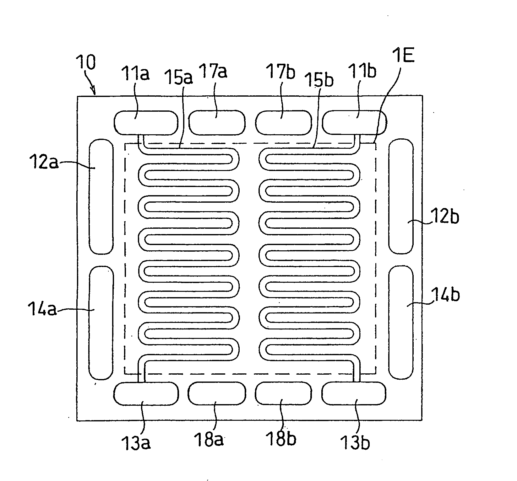
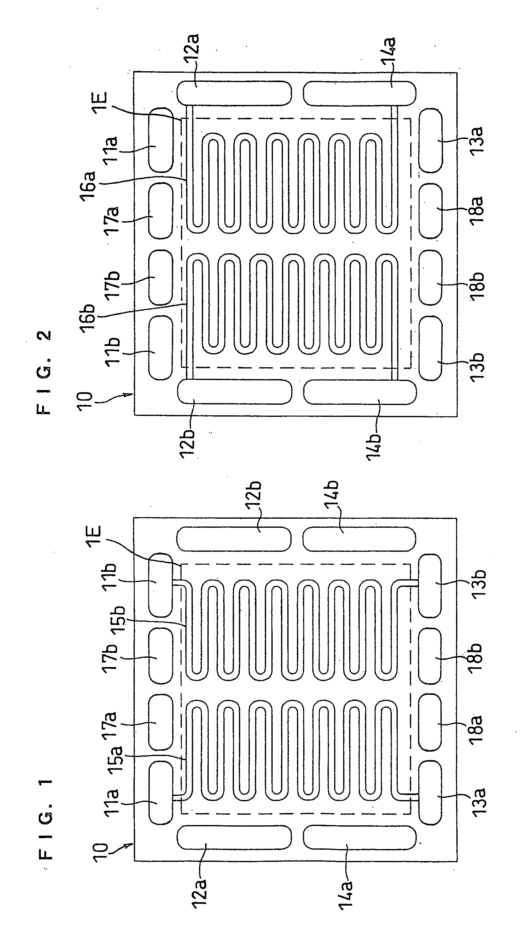
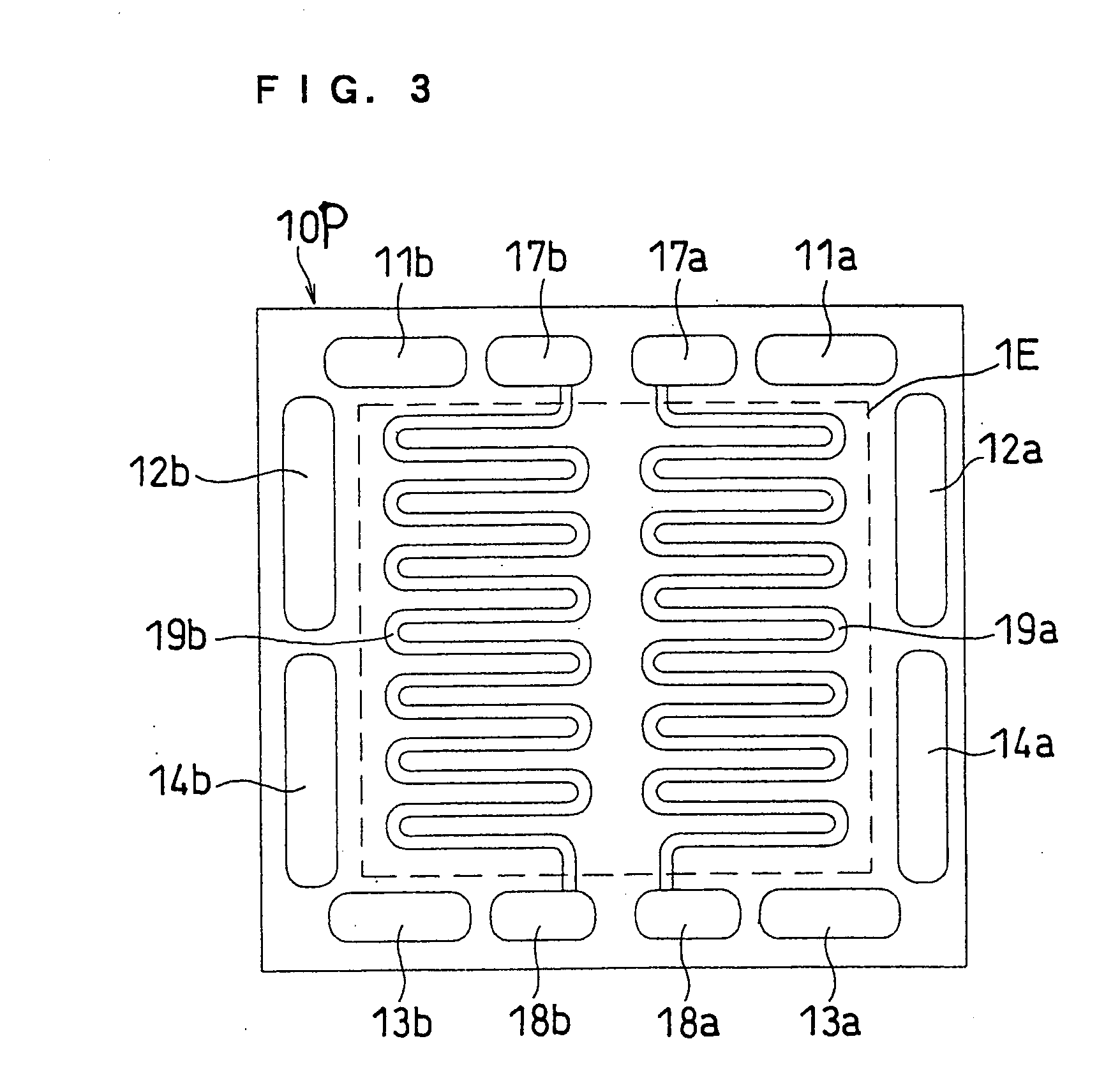
[0071] FIGS. 1, 2 and 3 illustrate separator plates of this embodiment. FIG. 1 is a front view of the anode facing side of a separator plate 10, and FIG. 2 is a back view thereof as well as a front view of the cathode facing side. FIG. 3 is a front view of a cathode facing side of an anode side separator plate 10P including a cooling section.
[0072] A separator plate 10 has fuel gas inlet-side manifold apertures 11a and 11b, fuel gas outlet-side manifold apertures 13a and 13b, oxidant gas inlet-side manifold apertures 12a and 12b, oxidant gas outlet-side manifold apertures 14a and 14b, cooling water inlet-side manifold apertures 17a and 17b, and cooling water outlet-side manifold apertures 18a and 18b. The separator plate 10 has, on the anode facing side, independent fuel gas flow channels 15a and 15b communicating with the inlet-side manifold apertures 11a and 11b and the outlet-side manifold apertures 13a and 13b, respectively. On the cathode facing side, the sep...
embodiment 2
[0080] Embodiment 2
[0081] This embodiment describes an example of dividing each of the fuel gas flow channel and the oxidant gas flow channel into two parts, such that the area ratio of the flow channel regions of the two divided gas flow channels is 2:1. The flow channel regions in which the independent gas flow channels are located may be different or the same in area (size), as necessary. The term "flow channel region" as used herein refers to the region of a separator plate at which each flow channel is located. The area ratio is based on the areas of the flow channels projected onto the plane of the separator plate. The cross-sections of the different flow channels may be the same or different. If the cross-sections are the same, an area ratio of 2:1 indicates that there is also a length ratio of about 2:1. In any event, the flow channels may have the same or different total volumes, and the same or different total volumes may be provided by varying the cross-section or length ...
embodiment 3
[0084] Embodiment 3
[0085] FIGS. 7 and 8 illustrate a separator plate of this embodiment. This is an example of dividing the electrodes of an MEA into two physically separate sections, in correspondence with the two divided gas flow channels. The physical separation between the two electrode sections prevents or diminishes migration of water and reaction gases from one electrode section to the other. The physical separation can be provided by an air gap between the electrode sections or by interposing a water-impermeable material and a reaction gas-impermeable material therebetween. An electrode section 1Ea of the MEA is provided in agreement with the fuel gas flow channel 15a and the oxidant gas flow channel 16a, while an electrode section 1Eb is provided in agreement with the fuel gas flow channel 15b and the oxidant gas flow channel 16b. Except for these electrode sections 1Ea and 1Eb, this embodiment has the same constitution as that of Embodiment 1.
PUM
 Abstract
Description
Claims
Application Information
 - R&D
- Intellectual Property
- Life Sciences
- Materials
- Tech Scout
- Unparalleled Data Quality
- Higher Quality Content
- 60% Fewer Hallucinations
Browse by: Latest US Patents, China's latest patents, Technical Efficacy Thesaurus, Application Domain, Technology Topic, Popular Technical Reports.
© 2025 PatSnap. All rights reserved.Legal|Privacy policy|Modern Slavery Act Transparency Statement|Sitemap|About US| Contact US: help@patsnap.com


