

Multiheaded hook
a hook and multi-headed technology, applied in the field of multi-headed hooks, can solve the problems of limiting the individual hooks, limiting the strength of the engaging head portion of the hook element, and generally expensive and coarse to the touch, so as to reduce the thickness of the hook member, reduce the thickness, and reduce the molecular orientation of the hook member
- Summary
- Abstract
- Description
- Claims
- Application Information
AI Technical Summary
Benefits of technology
Problems solved by technology
Method used
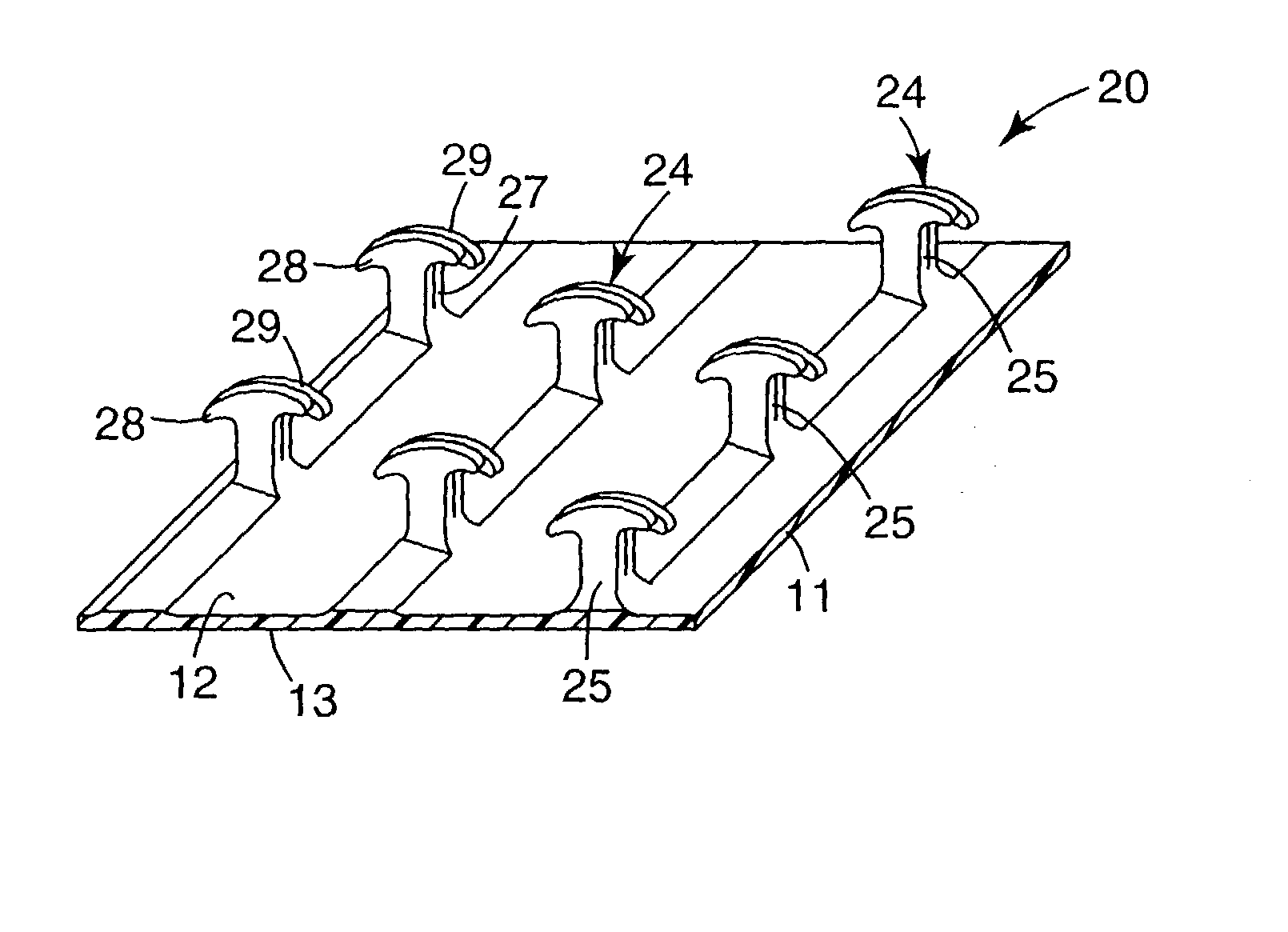
Image

Examples
example 1
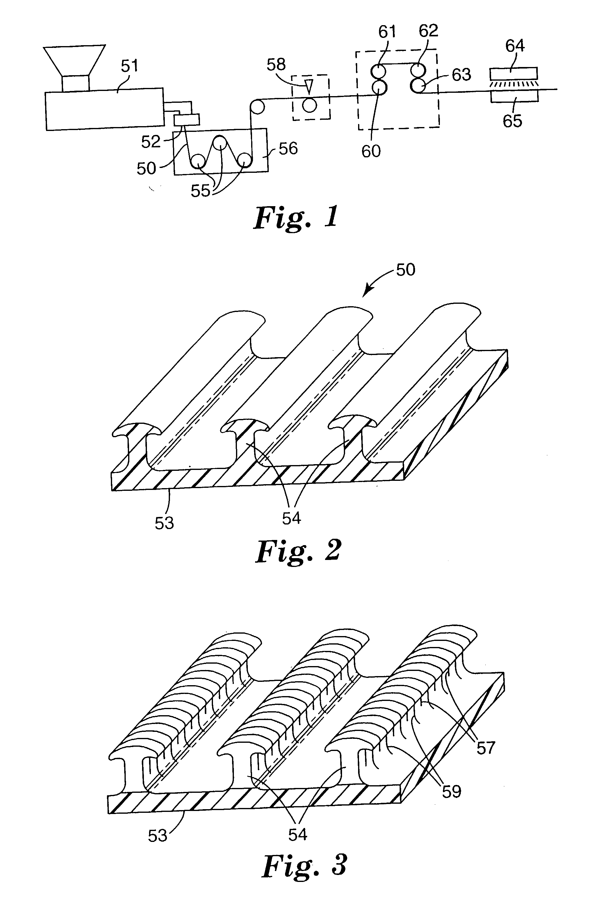
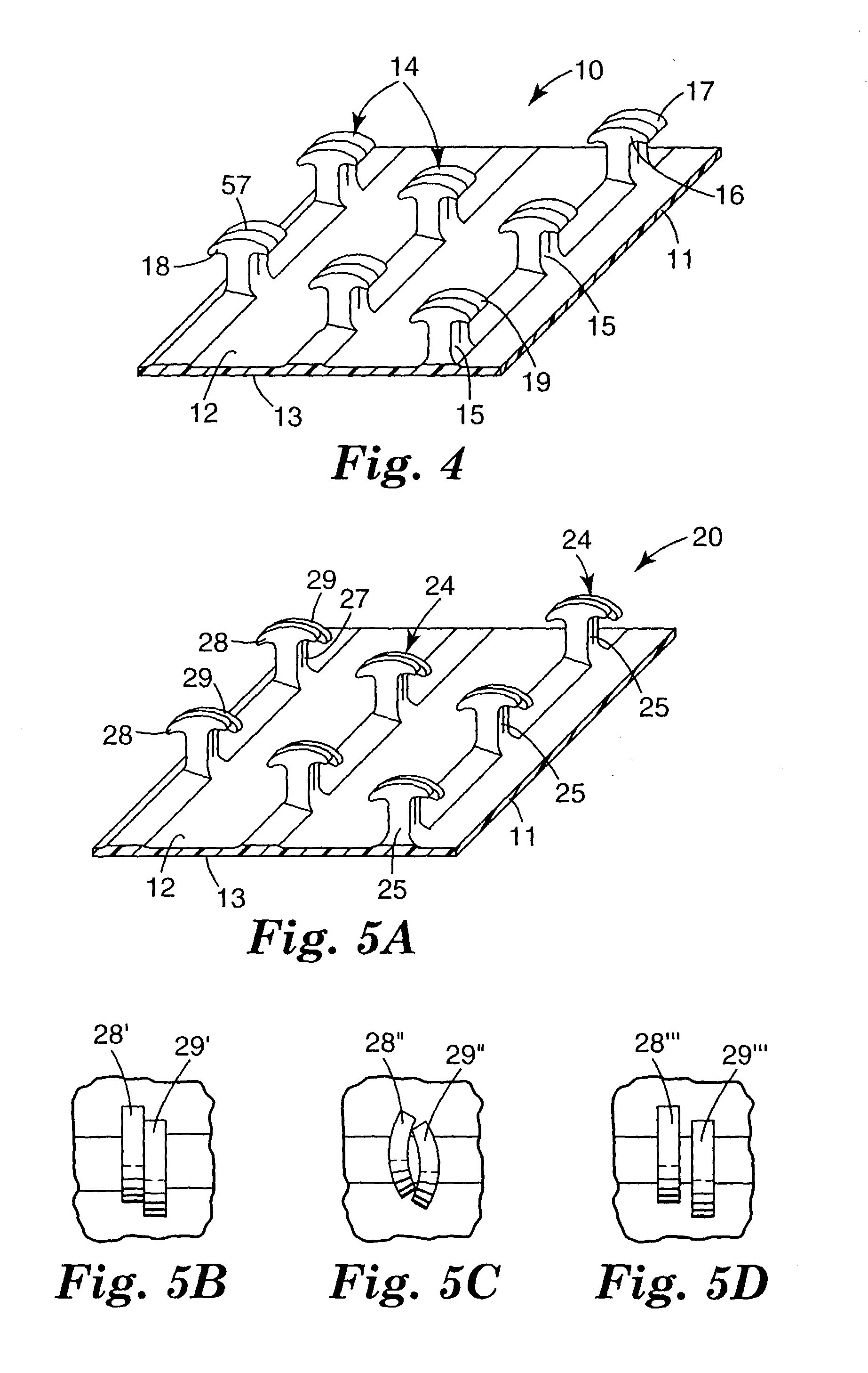
[0059] A unitary hook fastener web was made using apparatus similar to that shown in FIG. 1. A polypropylene / polyethylene impact copolymer (SRC7-644, 1.5 MFI, Dow Chemical) pigmented with 1% by weight of a polypropylene / TiO2 (50:50) concentrate, was extruded with a 6.35 cm single screw extruder (24:1 L / D) using a barrel temperature profile of 177.degree. C.-232.degree. C.-246.degree. C. and a die temperature of approximately 235.degree. C. The extrudate was extruded vertically downward through a die having an opening cut by electron discharge machining. After being shaped by the die, the extrudate is quenched in a water tank at a speed of 6.1 meter / min with the water being maintained at approximately 10.degree. C. The web was then advanced through a cutting station where the ribs (but not the base layer) were transversely cut at an angle of 23 degrees measured from the transverse direction of the web. The cutting apparatus was modified such that two different depths of cuts resulted...
example 2
[0060] A unitary hook fastener web was made as in Example 1 except the cutting apparatus was modified such that the spacing between the primary and secondary cuts was 305 microns. After cutting the ribs, the base of the web was longitudinally stretched at a stretch ratio of approximately 3.65 to 1 between a first pair of nip rolls and a second pair of nip rolls to further separate the individual hook elements to approximately 6 hook members / cm in the downweb direction.
example 3
[0061] A unitary hook fastener web was made as in Example 1 except the cutting apparatus was modified such that the repeat sequence of cuts in the downweb (machine direction) along a given rib was primary-secondary-primary-secondary, etc. The spacing of the cuts was 254 microns. After cutting the ribs, the base of the web was longitudinally stretched at a stretch ratio of approximately 3.65 to 1 between a first pair of nip rolls and a second pair of nip rolls to further separate the individual hook elements to approximately 5 hook members / cm in the downweb direction. Separation occurred only between the deeper primary cuts resulting in a series of hook elements downweb wherein every hook element had a secondary cut splitting the upper portion of the hook element into halves.
PUM
| Property | Measurement | Unit |
|---|---|---|
| width | aaaaa | aaaaa |
| width | aaaaa | aaaaa |
| width | aaaaa | aaaaa |
Abstract
Description
Claims
Application Information