Process for forming a protective coating containing aluminium and zirconium on a metal
a technology of aluminium and zirconium, applied in the direction of solid-state diffusion coating, vacuum evaporation coating, coating, etc., can solve the problem of no process which can be used industrially
- Summary
- Abstract
- Description
- Claims
- Application Information
AI Technical Summary
Problems solved by technology
Method used
Image

Examples
example 1
[0048] The procedure was as in the comparative example replacing the ammonium acid fluoride by an equivalent quantity (mole for mole) of zirconium oxychloride. On completion of the treatment a coating having a thickness of approximately 50 .mu.m was obtained. However, contrary to the previous instance, this deposit had three distinct zones. In the substrate, the interdiffusion zone, approximately 10 .mu.m thick, was conventional. This zone was overlain by a single-phase .beta.-NiAl coating approximately 40 .mu.m thick. Finally an additional zone approximately 10 .mu.m thick consisted of a matrix of .beta.-NiAl containing precipitates of chromium-zirconium. Analysis of the concentration profile over a thickness of 20 .mu.m by mass spectroscopy (glow discharge mass spectroscopy, GDMS) showed that the zirconium is concentrated in the first few micrometres and that its concentration in the rest of the coating was approximately 200 parts per million (ppm) by mass.
example 2
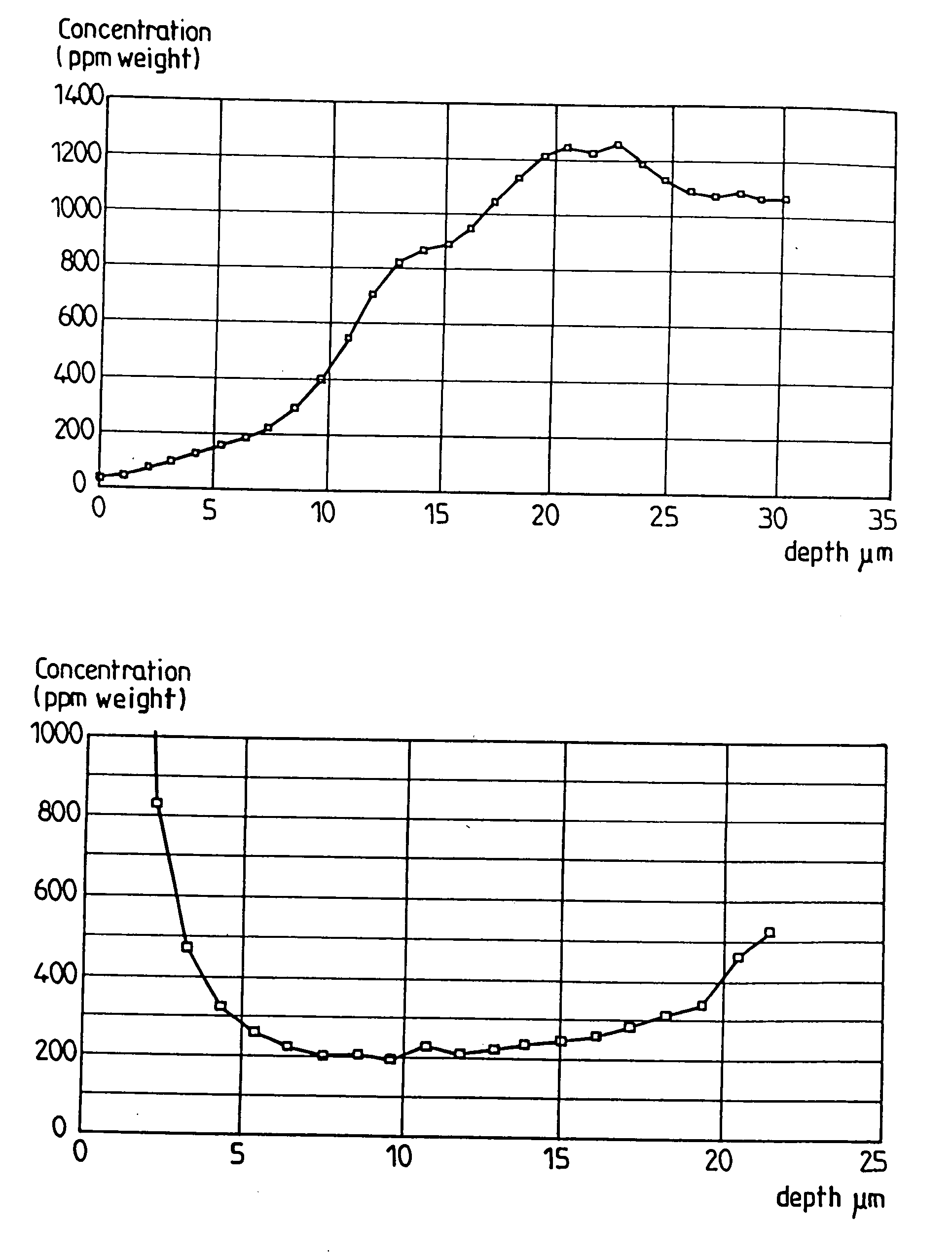
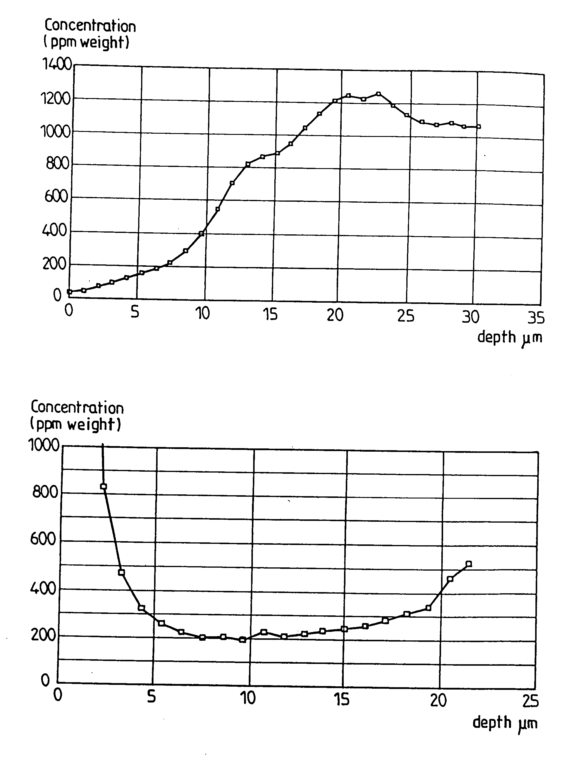
[0049] The procedure was as in example 1, replacing the aluminium-chromium donor cement containing 30% aluminium with a chromium-based cement containing 20% of aluminium. The purpose of this reduction in the activity of the aluminium was to enhance better distribution of the zirconium throughout the coating. As in the previous example the treatment temperature was 1080.degree. C. and the working atmosphere was hydrogen. However, in order to compensate for the low activity of the aluminium the treatment time was extended to 16 hours. On completion of this treatment a coating of approximately 50 .mu.m was obtained. This coating consisted of two parts--an interdiffusion zone of approximately 10 .mu.m containing the conventional TCP phases and a coating proper having a thickness of approximately 40 .mu.m and comprising a matrix of stoichiometric .beta.-NiAl containing zirconium in solid solution and free from precipitate. GDMS analysis yielded the zirconium concentration profile as show...
example 3
[0051] In this example it is the intention to demonstrate that it is possible to control the zirconium concentration obtained in the coating through mere dilution of the quantity of Zr-based activator. To effect this the procedure was as in the comparative example, replacing only part of the ammonium acid fluoride (the activator) by zirconium oxychloride. In this case the ZrOCl.sub.2 / NH.sub.4F,HF molar ratio was 1 / 9. Here also a nickel aluminide coating was obtained with a thickness of approximately 50 .mu.m with an interdiffusion layer of approximately 10 .mu.m and a layer of stoichiometric .beta.-NiAl 40 .mu.m thick. GDMS analysis over a depth of 20 .mu.m showed that the average zirconium content was less than in the previous example. Furthermore as the donor cement was different (higher activity), the concentration profile obtained was also different, as shown in FIG. 2.
PUM
| Property | Measurement | Unit |
|---|---|---|
| Fraction | aaaaa | aaaaa |
| Angle | aaaaa | aaaaa |
| Fraction | aaaaa | aaaaa |
Abstract
Description
Claims
Application Information