Cogeneration of organic compounds with synthesis gas by catalytic partial oxidation

Inactive Publication Date: 2004-10-07
CONOCOPHILLIPS CO
View PDF4 Cites 3 Cited by
  • Summary
  • Abstract
  • Description
  • Claims
  • Application Information

AI Technical Summary

Problems solved by technology

Wells that provide natural gas are often remote from locations with a demand for the consumption of the natural gas.
This transportation presents technological challenges due in part to the relatively large volume occupied by gaseous natural gas.
However, the expenditures associated with liquefaction are generally very high and liquefaction is not economical f

Method used


Image

  • Cogeneration of organic compounds with synthesis gas by catalytic partial oxidation
  • Cogeneration of organic compounds with synthesis gas by catalytic partial oxidation

Examples


Embodiment Construction

[0031] The following are examples of specific operating conditions and results in accordance with embodiments of the present invention.

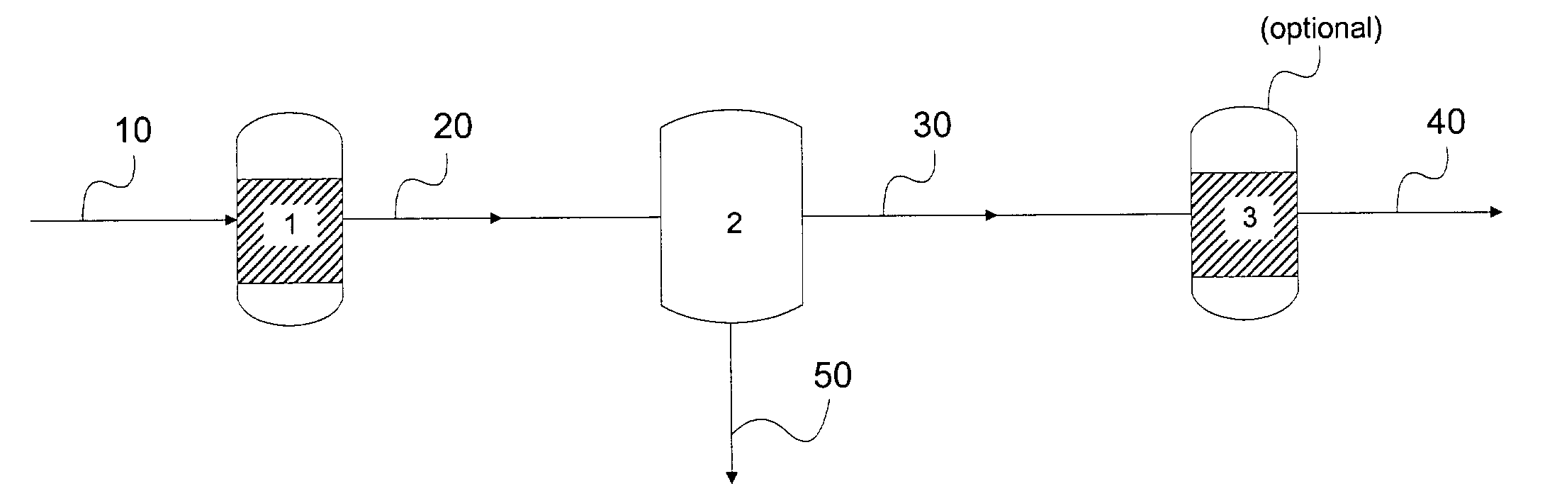
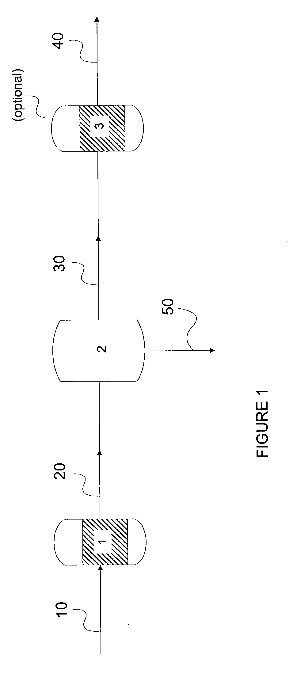
[0032] The syngas catalysts were tested at a methane:oxygen molar ratio of 1.82:1 at gas hourly space velocities (GHSV) of about 400,000 to about 2,700,000 hr.sup.-1, at pressures of about 45 psig to about 225 psig, respectively, and at temperature between 750.degree. C. and 1250.degree. C. for several days. The hydrocarbon gas (methane) was pre-heated and then mixed with O.sub.2 so that the average temperature of the feedstream reaches a temperature around 200-300.degree. C. before it contacts the catalyst. The catalytic partial oxidation reaction was carried out in a conventional flow apparatus using a 12.7 mm I.D. quartz insert embedded inside a refractory-lined steel vessel. The quartz insert contained a catalyst bed (2 g-5 g) containing a 9.5 mm to 30 mm catalyst bed held between two inert 80 -ppi alumina foams. The effluent steam from the react...


PUM

PropertyMeasurementUnit
Timeaaaaaaaaaa
Angleaaaaaaaaaa
Angleaaaaaaaaaa

Abstract

Disclosed herein are methods and apparatuses for cogenerating organic compounds (e.g., benzene, toluene, xylene, formate, acetate, propionate, butyrate, C1-C4 acids, C1-C4 alcohols, methanol, naphthalene, acenaphthylene, fluorene, phenanthrene, anthracene, fluoranthene, and pyrene) along with synthesis gas in a synthesis gas reactor, preferably a catalytic partial oxidation reactor.

Description

[0001] Not applicable.[0002] Not applicable.[0003] The present invention relates to processes and apparatus for the cogeneration of synthesis gas and organic compounds and to the synthesis gas and organic compounds produced by the processes and apparatus.[0004] Natural gas, found in deposits in the earth, is an abundant energy resource. For example, natural gas commonly serves as a fuel for power generation or a fuel for domestic use. The process of obtaining natural gas from an earth formation typically includes drilling a well into the formation. Wells that provide natural gas are often remote from locations with a demand for the consumption of the natural gas.[0005] Thus, natural gas is conventionally transported large distances from the wellhead to commercial destinations in pipelines. This transportation presents technological challenges due in part to the relatively large volume occupied by gaseous natural gas. Therefore, the process of transporting natural gas typically inclu...

Claims


Application Information

Patent Timeline
IPC IPC(8): C07C2/84C07C29/151C07C51/215C07C67/39
CPCC07C2/84C07C29/1518C07C51/215C07C67/39C07C2523/46C07C15/02C07C53/00C07C31/04Y02P20/52
Inventor STRAGUZZI, GLORIA I.WOLF, MARY E.WRIGHT, HAROLD A.
Owner CONOCOPHILLIPS CO
Why Eureka
Try Eureka