Processes for the production of electrophoretic displays

a technology of electrophoretic display and process, which is applied in the direction of liquid/fluent solid measurement, fluid pressure measurement, peptide, etc., can solve the problems of inadequate service life of electrophoretic display, preventing their widespread use, and insufficient prior art techniques for forming

Active Publication Date: 2004-11-18
E INK CORPORATION
View PDF99 Cites 160 Cited by
  • Summary
  • Abstract
  • Description
  • Claims
  • Application Information

AI Technical Summary

Problems solved by technology
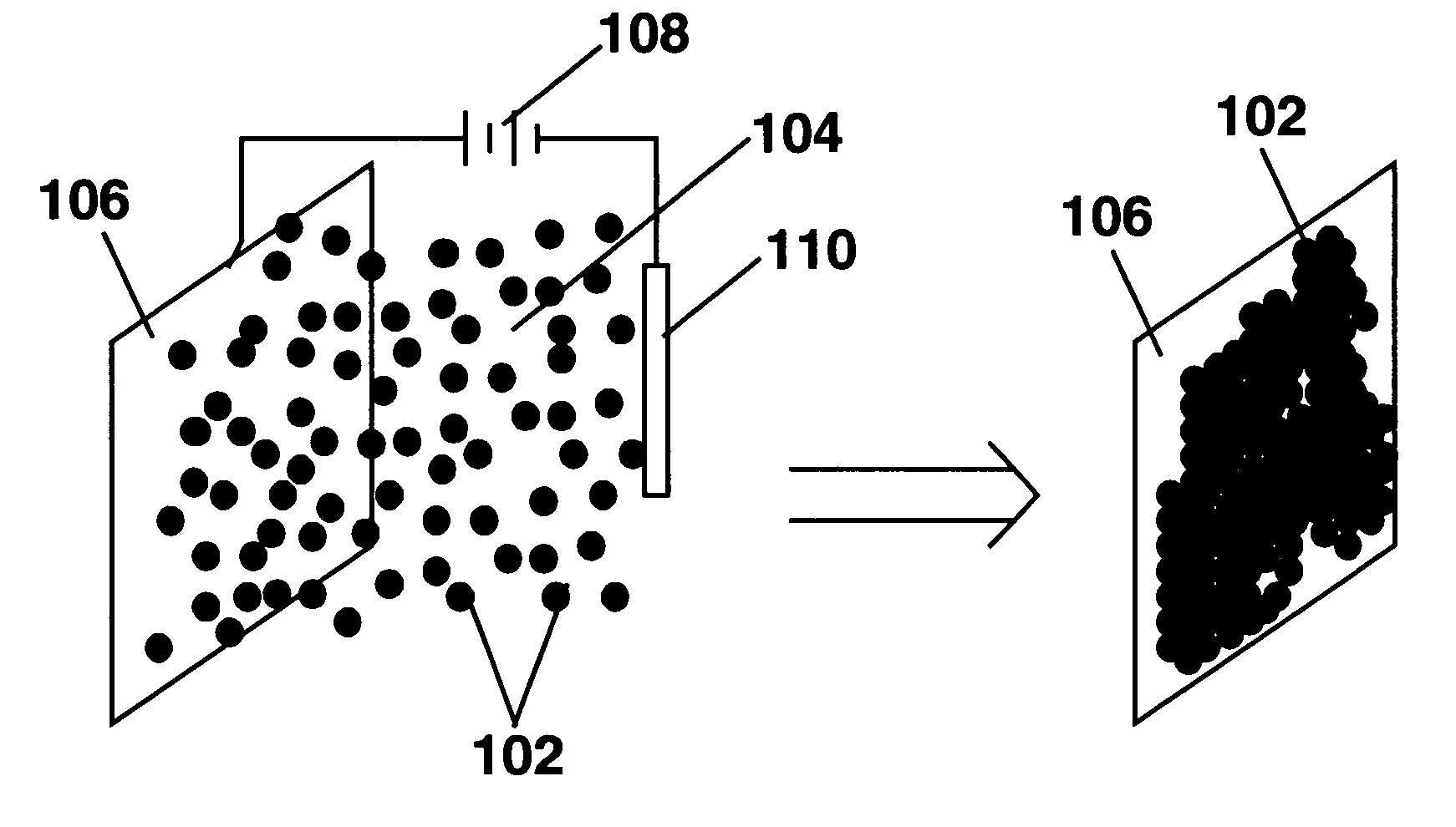
Nevertheless, problems with the long-term image quality of these displays have prevented their widespread usage.
For example, particles that make up electrophoretic displays tend to settle, resulting in inadequate service-life for these displays.
However, as already mentioned these prior art techniques are not satisfactory for forming, on arbitrary three-dimensional shapes, electrophoretic medium coatings with a sufficiently uniform thickness to give optimum optical performance.
While coating methods such as dip or spray coating can be applied to arbitrary three-dimensional shapes, it is difficult to or impossible to achieve uniform capsule monolayers over the substrate surface using these coating techniques.
Other problems encountered with slot coating techniques include:
The presence of these types of defects can adversely affect the appearance and optical performance of the display.
Also, as is well known to those skilled in slot coating technology, slot coating imposes limitations upon the viscosity and other physical properties of the material being coated, and typically requires the addition of slot coating additives to control the rheology of the coated material to ensure that the coating does not flow and develop non-uniformities in thickness prior to drying.
Although the binder serves several useful functions, including ensuring adequate adhesion of the capsule film to the substrate on which it is coated, excessive amounts of binder can hinder capsule contact with the electrode which is normally present on the substrate, and may also hinder the desirable flattening of the faces of the capsules in contact with the conductive coating (see, for example, the aforementioned U.S. Pat. No. 6,067,185).
Because the binder typically has a substantial effect on the viscosity and other physical properties of the capsule / binder mixture, at least in some cases it may be difficult to reduce the amount of binder used and still maintain these physical properties at values compatible with slot coating.
However, while conventional printing techniques might be used to prepare large displays of this type having resolutions of (say) less than 10 lines per inch (approximately 0.4 lines per mm), producing high resolution displays of this type with resolutions of about 100 lines per inch (approximately 4 lines per mm) with such conventional techniques is very difficult.
Again, while spray or ink jet coating might be used to apply the patterned coatings of capsules, producing monolayer capsule coatings using these methods will be difficult or impossible.

Method used


Image

  • Processes for the production of electrophoretic displays
  • Processes for the production of electrophoretic displays
  • Processes for the production of electrophoretic displays

Examples


example 2

Effect on Deposition of Electrode Material

[0108] The electrophoretic deposition experiments of Example 1 were repeated using glass / ITO, poly(ethylene terephthalate) (PET) / ITO, platinum, chrome, and copper substrates. In all cases, coatings were achieved by adjusting slurry pH and / or the encapsulation conditions, but all coatings without binder were typically limited to less than monolayer coverages of 65-80% after washing. This list of electrode materials on to which capsules can be electrophoretically deposited and adhered is not comprehensive; many more materials could presumably be coated by adjusting slurry pH, or capsule chemistry to promote the electrochemistry with a particular surface material that results in adhesion. The surfaces used were not intentionally patterned in any way to aid deposition; however, it was observed that in some cases apparent defects on the surface were preferentially coated with capsules (fabrication of patterned coatings is discussed in Example 9 b...

example 3

Electrochemical Degradation

[0109] As already noted significant electrochemical degradation of the positive electrode (deposition substrate) was observed to occur with certain electrode materials; this was most evident with substrates where a very thin conductive layer was deposited onto a nonconductive support, for example ITO on PET or chrome on glass. It was found that significant electrode degradation could interrupt the deposition process or cause highly laterally non-uniform coatings to develop. Generally as deposition proceeds, for example at constant voltage, electrochemical degradation can be recognized as a rapid decrease in current (vice versa for constant current conditions). Note that at constant current (with a suitable high voltage current source) deposition and electrochemical process proceed until the electrode fails catastrophically, whereas at constant voltage, the deposition process and degradation slow down as the experiment proceeds because the current drops off...

example 4

Effects of Binder

[0111] Experiments similar to those carried out in Example 1 above were performed with the addition of a binder to the capsule slurry. The binder used was a polyurethane latex dispersion in which the latices were stabilized by negative surface charge so that the binder deposited on the positive electrode along with the capsules. The charging chemistry for this binder required a pH of at least 7-8, so all capsule slurries containing the binder were prepared at least at pH>7. As noted in Example 3, high pH negatively impacted degradation of the ITO electrode surface, so it was necessary to prepare coatings on glass / ITO electrodes that had thicker ITO coatings, thickness approximately 200 nm.

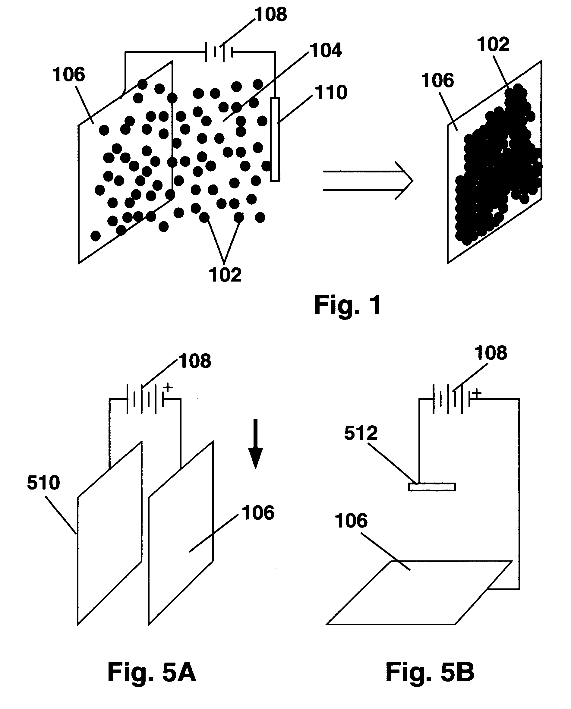
[0112] The electrodeposition experiments were conducted using the vertical apparatus of FIG. 5A; the applied voltage was constant at 4 V and deposition time was varied. The surface area coated (A.sub.coat) was typically about 2.5 to 3.75 cm.sup.2. The ratio of capsules to binder wa...


PUM

PropertyMeasurementUnit
conductivityaaaaaaaaaa
pHaaaaaaaaaa
roughnessaaaaaaaaaa

Abstract

A coating of an encapsulated electrophoretic medium is formed on a substrate (106) by dispersing in a fluid (104) a plurality of electrophoretic capsules (102), contacting at least a portion of a substrate (106) with the fluid (104); and applying a potential difference between at least a part of the portion of the substrate (106) contacting the fluid (104) and a counter-electrode (110) in electrical contact with the fluid (104), thereby causing capsules (102) to be deposited upon at least part of the portion of the substrate (106) contacting the fluid (102). Patterned coatings of capsules containing different colors may be deposited in registration with electrodes using multiple capsule deposition steps. Alternatively, a patterned coating may be deposited upon a substrate containing a conductive layer by varying the conductivity of the conductive layer by radiation exposure or by coating portions of the conductive layer with an insulating layer, typically a photoresist.

Description

REFERENCE TO RELATED APPLICATIONS[0001] This application claims benefit of Provisional Application Serial No. 60 / 320,050, filed Mar. 25, 2003, and of Provisional Application Serial No. 60 / 481,550, filed Oct. 23, 2003.[0002] This application is also related to copending application Ser. No. 09 / 349,806, filed Jul. 8, 1999.[0003] The entire contents of these copending applications, and of all other U.S. patents and published and copending applications mentioned below, are herein incorporated by reference.BACKGROUND OF INVENTION[0004] This invention relates to processes for the production of electrophoretic displays.[0005] The term "electro-optic", as applied to a material or a display, is used herein in its conventional meaning in the imaging art to refer to a material having first and second display states differing in at least one optical property, the material being changed from its first to its second display state by application of an electric field to the material. Although the o...

Claims


Application Information

Patent Timeline
Patent Type & Authority Applications(United States)
IPC IPC(8): C25D13/00G02F1/167G02F1/16757G02F1/1679
CPCC25D13/00G02F1/167G02F1/1679G02F1/16757
Inventor WEBBER, RICHARD M.WHITESIDES, THOMAS H.DANNER, GUY M.HERB, CRAIG A.HONEYMAN, CHARLES H.MCCREARY, MICHAEL
Owner E INK CORPORATION
Why Eureka
Try Eureka