Method and apparatus for the estimation of the temperature of a blackbody radiator

a blackbody radiator and temperature estimation technology, applied in the direction of optical radiation measurement, interferometric spectrometry, instruments, etc., can solve the problems of affecting the accuracy of the estimation of the emissivity, the inferred temperature can be substantially in error, and the current ftir spectroscopy does not, so as to improve the signal to noise ratio (snr)

Inactive Publication Date: 2004-12-02
AUSTRALIEN NAT UNIV
View PDF7 Cites 17 Cited by
  • Summary
  • Abstract
  • Description
  • Claims
  • Application Information

AI Technical Summary

Benefits of technology

[0051] Preferably, the frequency of modulation of the optical path length is away from the low-frequency "l / f", or flicker noise associated with photoconductors. Modulation of the interferogram signal allows the use of synchronous detection techniques to improve the signal to noise ratio (SNR), which is inversely proportional to the square root of the detection bandwidth.

Problems solved by technology

One consequence of the dependence of the temperature uncertainty on errors in the estimated emissivity is that a 10% inaccuracy in the estimate of the emissivity can give rise to errors of the order of a few percent in the inferred temperature (in degrees Kelvin).
In addition, the inferred temperature can be substantially in error if the radiating source does not fill the field of view of the measurement system.
However, current FTIR spectroscopy does have some disadvantages.
They can also be bulky and sensitive to external noise, and require a computer for Fourier inversion of the interferogram and display of the spectrum.
They are not readily configurable as imaging devices; they have limited field-of-view; and they usually require optical path length monitoring using a suitable fixed wavelength source such as a laser.

Method used


Image

  • Method and apparatus for the estimation of the temperature of a blackbody radiator
  • Method and apparatus for the estimation of the temperature of a blackbody radiator
  • Method and apparatus for the estimation of the temperature of a blackbody radiator

Examples


Embodiment Construction

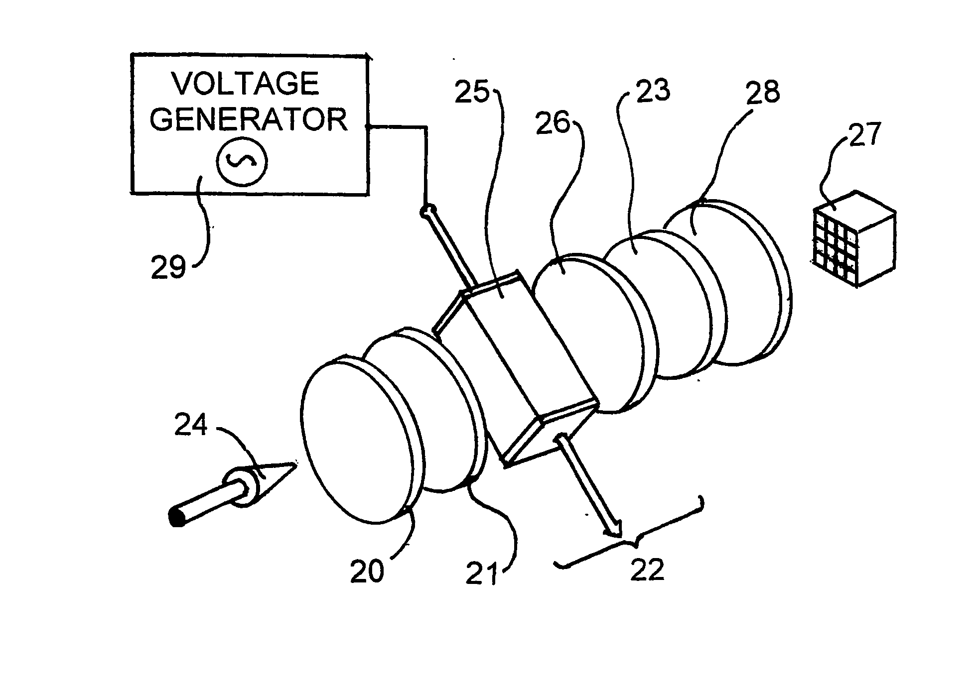
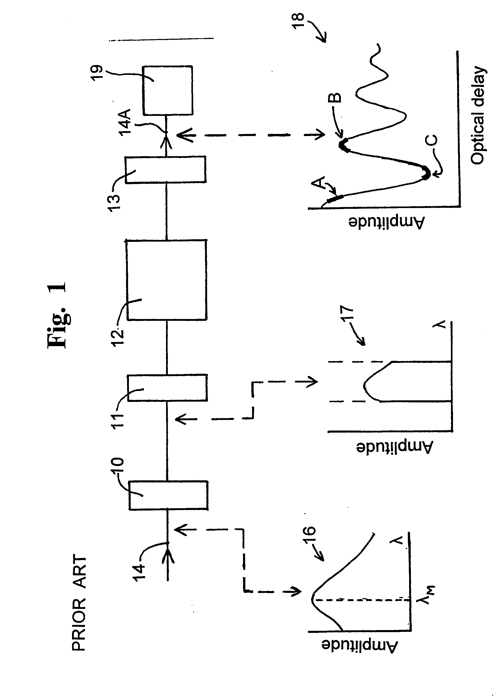
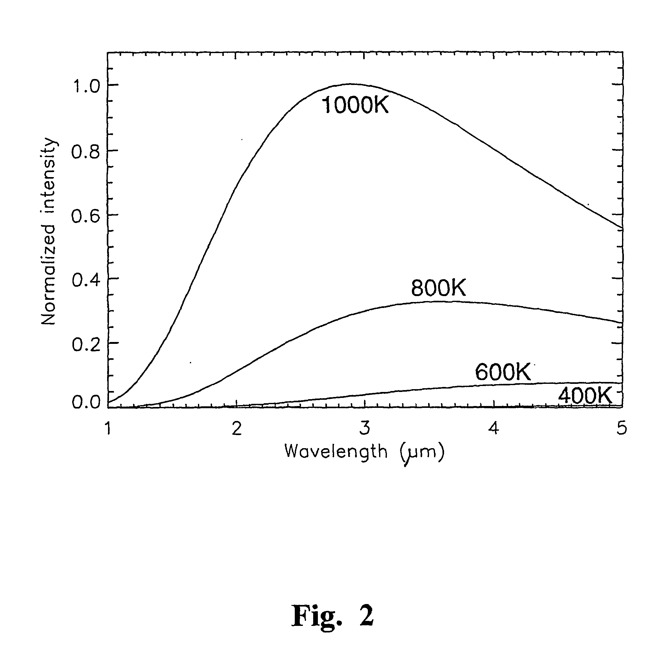
[0060] Part of the emission spectra of several blackbody radiators is shown in FIG. 2. If radiation from these radiators is passed through an electro-optical filter as shown in FIG. 1, with the band pass filter 10 being a top hat band pass electro-optical filter, spanning the range of from 1 to 5 .mu.m, the resultant fringe pattern of the interferogram of the output radiation 15 (shown as a plot of intensity of the received radiation against the delay introduced by the electro-optical filter) is as shown in FIG. 3. FIG. 3 is, in fact, the Fourier transform of the emission spectra of FIG. 2.

[0061] It is clear from FIG. 1 that, as noted above, it is the shape of the interferogram near zero delay that is most closely related to the source temperature. At the offset delay, or operating point, below the first interferogram zero, shown by the region A in the graphical representation 18 of FIG. 1, the slope of the interferogram increases with temperature, while the fringe visibility decrea...


PUM


Abstract

Remote sensing of the temperature of a greybody or blackbody radiator is effected by passing its radiation (24) through a modulated infrared filter spectrometer. The infrared filter comprises, in sequence, a band pass filter (20), a first polariser (21) which polarises the radiation, an electro-optical element (22) which splits the polarised radiation into two orthogonally polarised components, and a second polariser (23). A lens (28) images the radiation leaving the second polariser onto a detector (27). The electrical signal from the detector (27) is input to a numerical analyser. The electro-optical element (22), typically comprising a birefringent crystal assembly (25) and a birefringent trim plate (26), is configured so that the net optical delay of the orthogonally polarised components passed through it is such that the recombined components are at or near a peak or trough in their interferogram. A sinusoidally varying voltage is applied to the electro-optical element to modulate the net delay of the components passed through the electro-optical element. The numerical analyser is programmed to compute the harmonic amplitude ratio (the ratio of signal amplitudes at the fundamental and second harmonic of the frequency of the modulating voltage) of the signal that it receives from the detector (27). The harmonic amplitude ratio is a function of the temperature of the radiator, which can be estimated by reference to a calibration look-up table.

Description

[0001] This invention concerns the estimation, by remote observation, of the temperature of a blackbody or a greybody radiator. More particularly, it involves the estimation of the temperature of a radiator by a relatively low resolution spectral technique, using a novel form of optically filtered and electro-optically modulated interferometer. The interferometer or spectrometer (which is one aspect of the present invention), operates in the infrared and / or visible region of the electromagnetic spectrum. The method of the invention involves the processing of a selected region of the interferogram produced by the filter spectrometer.BACKGROUND TO THE INVENTION[0002] Non-contact optical thermometry is a rapidly growing field with applications in remote-sensing of hostile or corrosive environments, medical imaging, environmental studies and industrial process monitoring. The current best practice in remote temperature sensing involves the use of cryogenic infrared radiometers.[0003] In...

Claims


Application Information

Patent Timeline
Patent Type & Authority Applications(United States)
IPC IPC(8): G01J3/45G01J5/00G01J5/60G02B5/30
CPCG01J3/45G01J5/00G01J5/0834G01J5/58G01J2005/583G01J2005/586G01J5/59G01J5/0804G01J5/0831
Inventor HOWARD, JOHN
Owner AUSTRALIEN NAT UNIV
Why Eureka
Try Eureka