In addition, since the technique of “the transparent
layer thickness irregularity correction function (thickness
servo)” has not been used in information playback apparatuses and information recording / playback apparatuses, “the residual deviation amount (the upper limit of an allowable residual deviation amount) required for stable operation in transparent
layer thickness irregularity correction function (thickness servo)” is completely unknown information in the past servo techniques.
If the NA value is increased to 0.65 or more to increase the
recording density in a next-generation DVD, a single-lens structure cannot be used owing to a problem in terms of a manufacturing technique for objective lenses, and an objective lens structure constituted by two or more lenses is required.
This makes it difficult to use the same manufacturing method (
quality control method) as that for an information medium used for a conventional DVD.
However, such a mechanical measurement method is not suited to measuring and managing the above thin (0.1 mm) transparent layer with high precision.
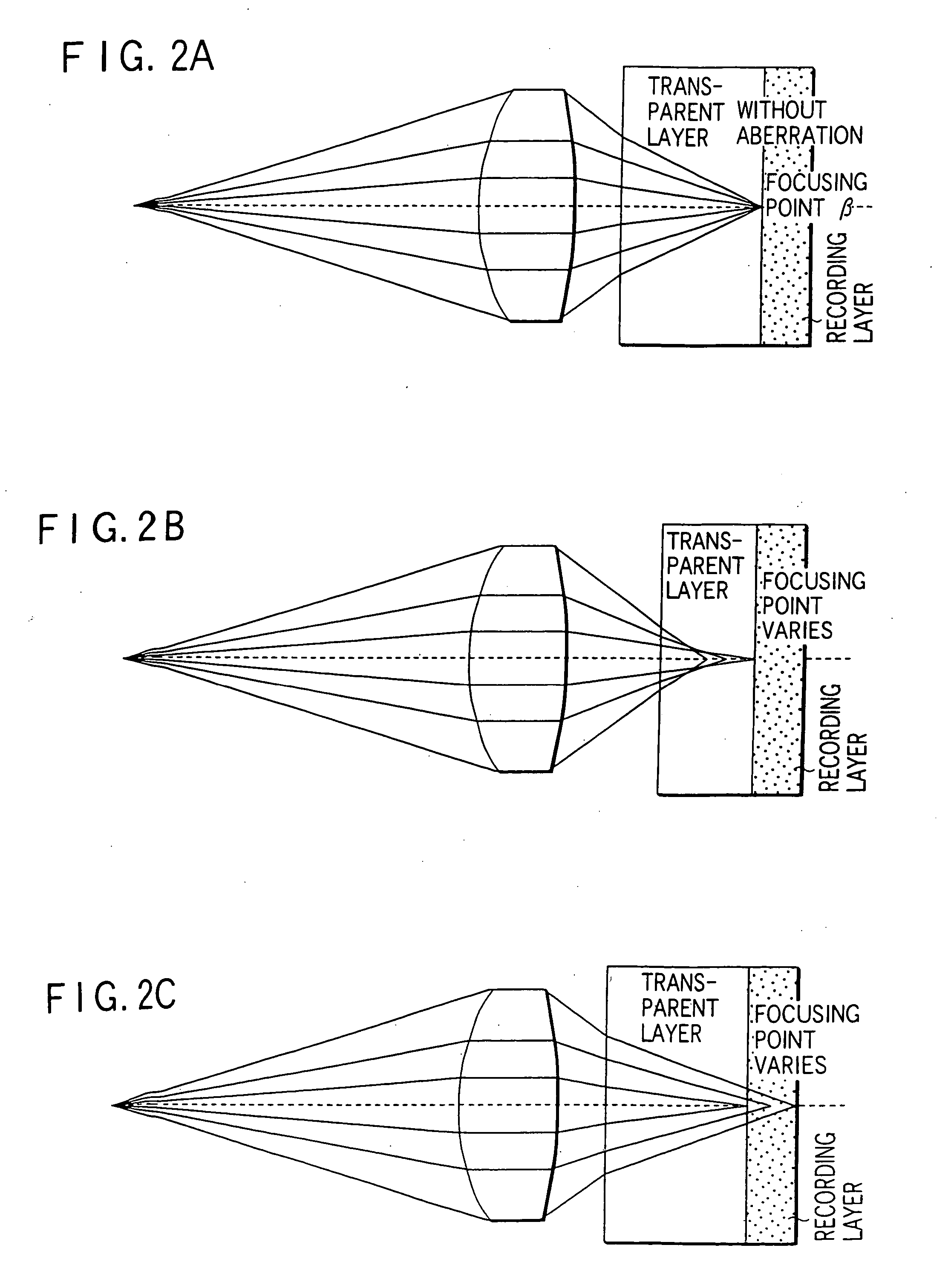
In defining a transparent
layer thickness irregularity allowable range in specifications, however, any method of measuring the thickness of a transparent layer portion has not yet been established.
Since this method is a destructive measurement method for an information medium, the information medium cannot be used after the measurement (destruction of part of the transparent layer).
In addition, there is no information as to what to do about the characteristics (e.g., the relationship between thickness and
refractive index) of the transparent layer of an information medium (optical disk) whose transparent layer has thickness irregularity in an allowable range.
In this case, however, the following problems arise: If the distance between the two
layers is reduced, light reflected by one reflecting layer or recording layer leaks into the
photodetector while information is played back from the other reflecting layer or recording layer, resulting in interlayer
crosstalk and a deterioration in playback
signal.
If the precision of the thickness from the disk surface to each layer is strictly managed, the manufacturing yield of
information media (optical disks) decreases, resulting in an increase in the sales price of
information media.
It is therefore difficult to provide sufficient, stable
servo control, resulting in stricter requirement for the thickness irregularity allowable range for transparent
layers.
In addition, since the upper limit of servo response frequencies is restricted by a wobbling frequency, high-speed servo control is difficult to realize.
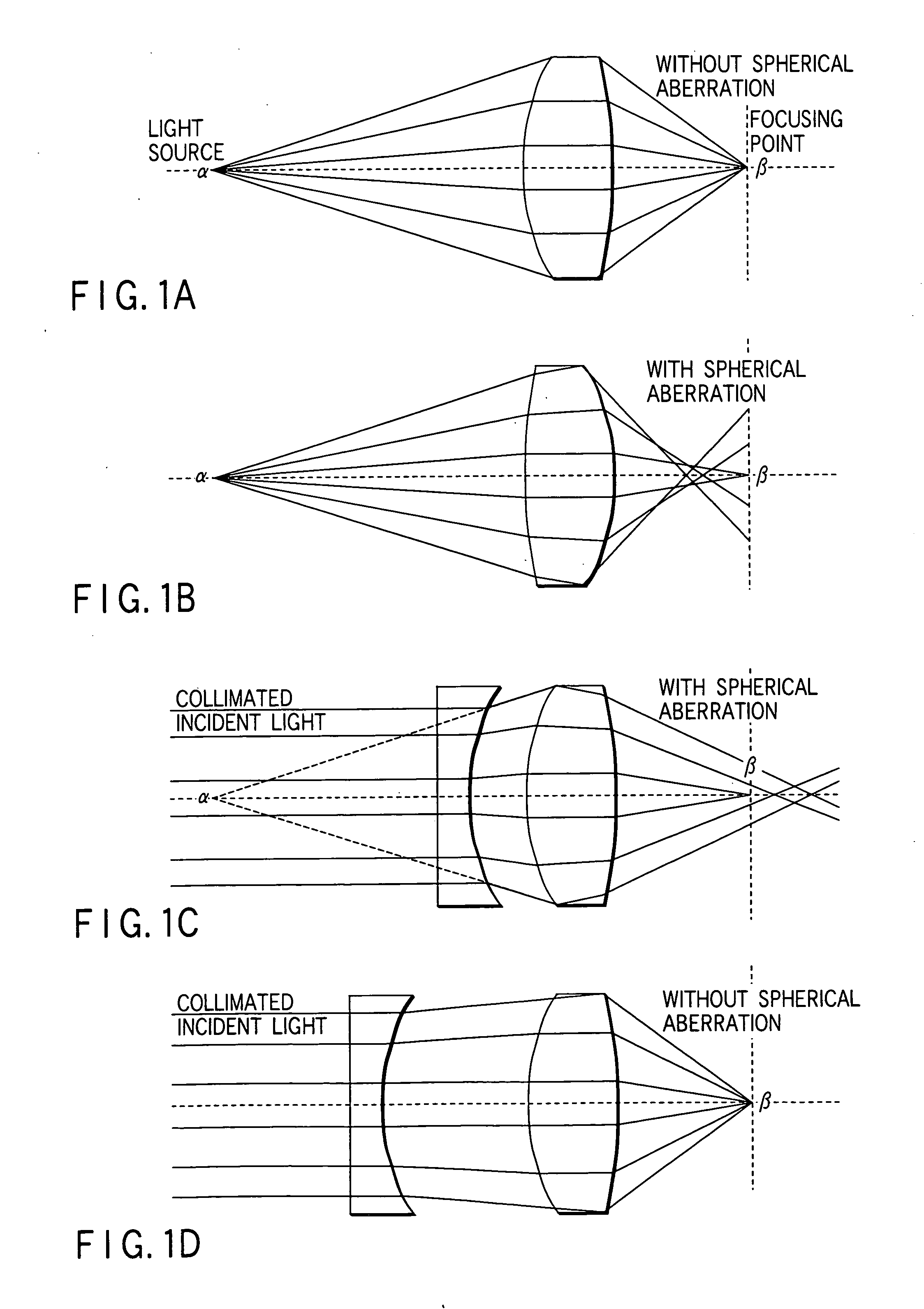
When this
coma occurs, the spot size of the focused light beam on the recording surface increases to cause a deterioration in playback signal from the optical disk (information medium) or
instability in recording on the optical disk (information medium) as in the case of the occurrence of
spherical aberration.
If, however, a thickness servo mechanism and / or tilt servo mechanism is additionally introduced, including their detection optical systems (in addition to the above DPP and / or CTC optical systems and circuit systems), the servo system (detection system and circuit system) is complicated accordingly, resulting in an increase in the cost of an optical head.

