Weldable conduit and method

a conduit and welding technology, applied in the direction of screw threaded joints, process and machine control, instruments, etc., can solve the problems of in-situ re-coating, high cost and time-consuming, and many pipe material protection problems, so as to inhibit the transfer of heat and reduce operation

Active Publication Date: 2005-01-13
HEAT PRO SYST
View PDF32 Cites 25 Cited by
  • Summary
  • Abstract
  • Description
  • Claims
  • Application Information

AI Technical Summary

Benefits of technology

[0021] It is also preferred that the tube of each conduit is formed of (i.e., includes to a substantial degree) an alloy containing one or more materials selected from the group of chromium, molybdenum, nickel, iron, copper, and titanium. In particular embodiments, the tube of each conduit is formed of an alloy selected from the group of stainless steel, hastelloy, inconel, incoloy, and monel.
[0022] It is further preferred that the tube of each conduit be affixed to the pipe prior to the reducing operation by tack welding or clamping the aligned ends thereof together.
[0023] It is further preferred that the reducing operation includes rolling the pipe of each conduit or forcing the pipe of each conduit through a die.
[0024] The inventive method enables another aspect of the present invention, in the form of a weldable conduit assembly. The assembly includes a pair of opposing composite conduits each having an inner tube formed of a material having desirable properties (e.g., resistance to corrosion and/or erosion), and an outer pipe formed of a commonly weldable material. The pipe encircles and is compressed upon the tube such that the inner surface of...

Problems solved by technology

Such pipe is commonly manufactured from alloy steels which have insufficient anti-corrosive and/or anti-erosive properties to withstand attack from the gasses and liquids which are passed therethrough.
Welding of the pipe ends presents several pipe material protection problems.
First, where the pipe is protected by a thin polymer coating, the heat generated during welding destroys the coating adjacent the weld joint.
This in-situ re-coating is expensive and time consuming.
When the pipe segment and adjacent pipe end are welded together, a portion of the protective coatings on the interior of the pipe and coupling are destroyed by the heat of the weld.
Additionally, if the coupling is damaged at any point, the entire pipe to which it is attached is rendered useless.
First, the coupling is metallic and therefore transfers a substantial amount of heat from the welding operation along the inner diameter of the pipe.
This heat can destroy the interior protective coating on the pipe at a substantial distance inwardly of the pipe end.
Additionally, the coupling itself is also subject to corrosion or erosion when exposed to the pipe liquids or gasses.
The mastic will also be partially destroyed by heat during welding operations, and the mastic may become disengaged from the coupling ends and expose any defects in the coupling coating to the erosive and corrosive pipe environment.
Further, the seal configuration on the coupling does not fully protect the weld area from the erosive and/or corrosive conditions within the pipe.
Likewise, when the pipe inner diameter is at the low side of the tolerance, the seal may be destroyed as the coupling is shoved into the pipe end, particularly if the seal is configured for the high end of the inner diameter tolerance.
Additionally, the mastic may interfere with the seating of the seals against the inner diameter of the pipe, which will allow pipe liquids and gasses to leach between the coupling and the pipe.
Finally, the bosses used to align the pipe ends and maintain the proper weld gap may, when sacrificially incorporated into the weld, reduce the strength of the weld and thereby reduce the effectiveness of the weld connection.
The corrosive nature of some fluids also limits the utility of pipelines or runs wherein the individual pipe segments are welded together.
The limiting factor on pipe length in chemical plant applications is the need to provide a barr...

Method used


Image

  • Weldable conduit and method
  • Weldable conduit and method
  • Weldable conduit and method

Examples


Embodiment Construction

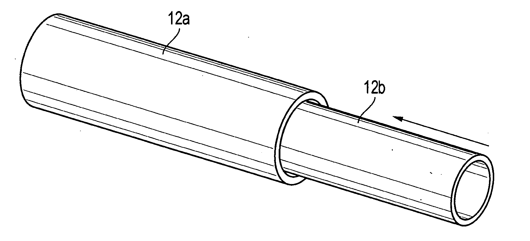
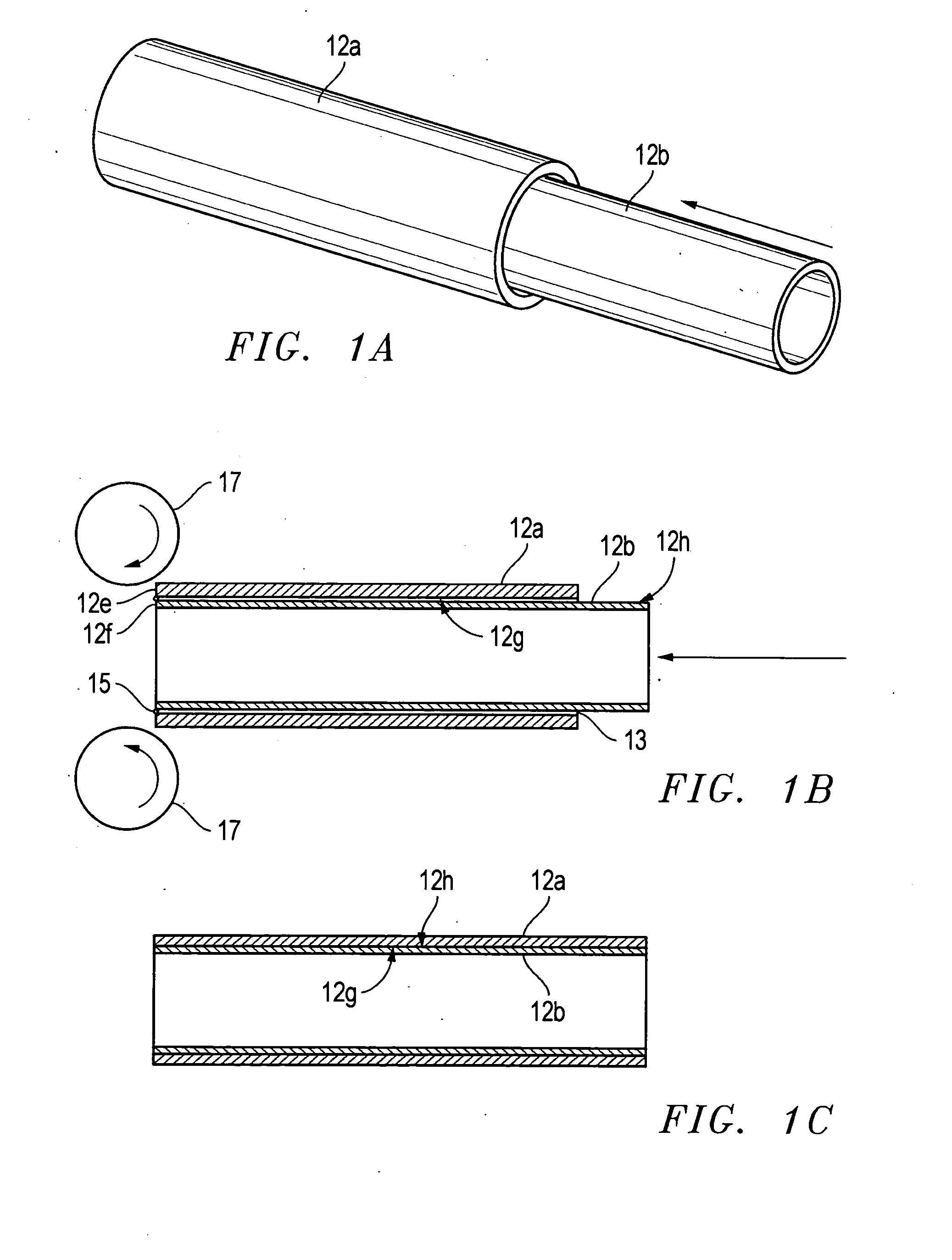
[0036] The present invention provides for the interconnecting by welding or flanged connection of tubular members employed for transporting corrosive and / or erosive fluids including gases, liquids or slurries. In one aspect, the invention provides a method of forming a weldable tubular member, referred to hereinafter as a “conduit.” With reference first to FIGS. 1A, 1B, and 1C, the inventive method includes the step of positioning a tube 12b formed of a material having desirable properties (e.g., resistance to corrosion and / or erosion) within a pipe 12a formed of a commonly weldable material. The tube 12b is preferably formed of (i.e., includes to a substantial degree) an alloy containing one or more materials selected from the group of chromium, molybdenum, nickel, iron, copper, and titanium, and, in certain embodiments, the tube is formed of an alloy selected from the group of stainless steel, hastelloy, inconel, incoloy, and monel. The pipe 12a is preferably formed of a carbon st...


PUM

PropertyMeasurementUnit
Volumeaaaaaaaaaa
Diameteraaaaaaaaaa
Electrical resistanceaaaaaaaaaa

Abstract

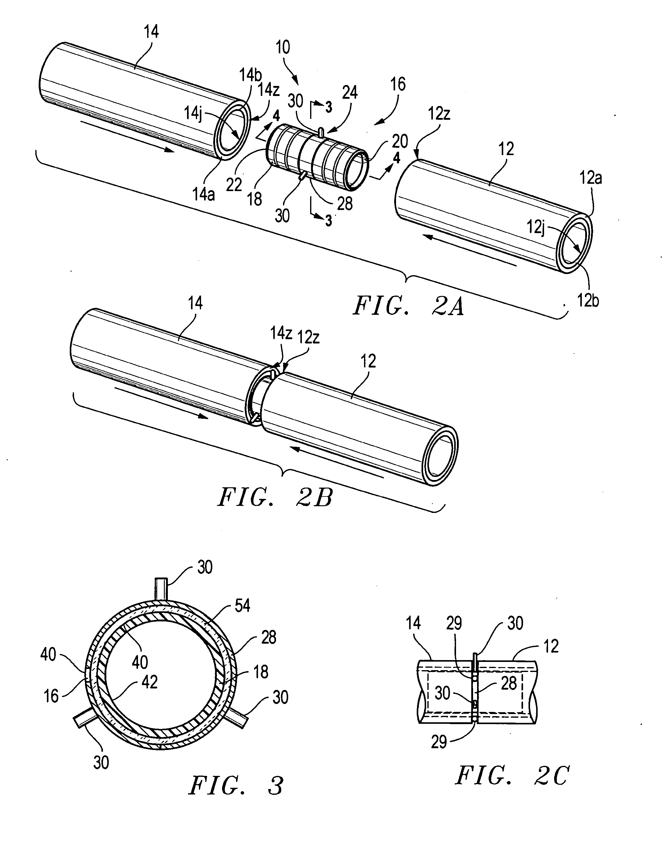
A composite conduit suitable for transporting corrosive and/or erosive fluids including gases, liquids or slurries, is formed by positioning a tube formed of a material having desirable corrosion and/or erosion resistant properties within a pipe formed of a commonly weldable material such that one end of the tube is aligned with one end of the pipe. The tube has an outer diameter slightly less than the inner diameter of the pipe. The tube is affixed to the pipe by connecting the aligned ends thereof, and the pipe is compressed in a reducing operation so that the inner diameter of the pipe is reduced to a diameter that is less than or equal to the outer diameter of the tube. Adjacent, end-to-end sections of the composite conduit are connected using a coupling that employs a cylindrical body formed of the same material as the tubes of the conduits. The coupling body has an outer diameter that is slightly less than the inner diameter of the tubes of the conduits, and preferably an inner diameter that varies to form a taper at each end of the body. The body further contains a circumferential recess intermediate the ends of the body, and a ring formed of the same material as the tubes of the conduits. The ring is positioned within the recess of the body and has a circumferential stop means for limiting movement of the ends of the body within the respective ends of the conduits by the ends of the conduits abutting the stop means. At least one circumferential seal is positioned intermediate the recess and each of the tapered ends of the body for sealing the interconnected conduits. An insulator is preferably positioned in the recess between the ring and the coupling body for inhibiting the transfer of heat produced by welding the ends of the conduits together, although the insulator is not essential in all embodiments.

Description

CROSS-REFERENCE TO RELATED APPLICATION [0001] This application is a continuation-in-part of prior, copending U.S. patent application Ser. No. 10 / 616,014 filed on Jul. 9, 2003.BACKGROUND OF THE INVENTION [0002] 1. Field of the Invention [0003] The present invention relates to the field of pipe connections. More particularly, the present invention relates to the field of welded pipe connections normally useful in the oil and gas production, and refining and transportation industries, as well as flanged pipe connections normally useful in the chemical plant industry. [0004] 2. Background of the Related Art [0005] Tubular goods, such as pipe used to transport oil and gas and products thereof, must be capable of withstanding the corrosive and / or erosive attributes of materials passing therethrough without failure. Such pipe is commonly manufactured from alloy steels which have insufficient anti-corrosive and / or anti-erosive properties to withstand attack from the gasses and liquids which...

Claims


Application Information

Patent Timeline
IPC IPC(8): B21C1/22B21C37/09B21C37/15F16L9/02F16L9/18F16L13/02F16L15/00F16L39/00
CPCB21C1/22B21C37/09B21C37/154F16L9/02Y10T29/49428F16L13/0227F16L39/00Y10T29/49904F16L9/18
Inventor LEWIS, JOHN K.
Owner HEAT PRO SYST
Why Eureka
Try Eureka