Compliant osteosynthesis fixation plate

a technology of fixation plate and osteosynthesis, which is applied in the field of prosthetic implants, can solve the problems of metal plate system being miniaturized and more biocompatible, affecting and affecting the use of metal, so as to maintain the structural rigidity of the device, retain enough structural rigidity and strength, and alter the physical characteristics of the prosthesis

Active Publication Date: 2005-01-20
DSM IP ASSETS BV
View PDF21 Cites 58 Cited by
  • Summary
  • Abstract
  • Description
  • Claims
  • Application Information

AI Technical Summary

Benefits of technology

[0028] The present invention takes advantage of the porous structure of the prosthesis that allows deformation of the device without cracking or breaking of the structure. When bending pressure, for example, is applied, individual pores will collapse, allowing the smooth bending of the prosthesis in a radius, rather than a sudden collapse of the material as the prosthesis breaks. Similarly, if compressive force is applied, a portion of the pores may collapse, allowing the prosthesis to conform to the shape of the tissue it is pressed against, while maintaining the structural rigidity of the device.
[0029] While allowing the flexibility to be custom fit to the patient's tissue contours at room temperature in the operating field without special tools, the prosthesis retains enough structural rigidity and strength to lend structural support and protect a healing wound of a patient, e.g., to serve as a tissue or bone fixation device, a skull plate, or other prosthesis requiring structural rigidity. By altering the construction, such as varying the pore size and number or incorporating reinforcement materials, the physical characteristics of the prosthesis can be altered. In this fashion, a tissue fixation device, e.g., a bone plate, that

Problems solved by technology

Over the years, metallic plate systems have become miniaturized and more biocompatible.
Despite the utility of metallic plate systems, their use is not without problems.
Multiple bending attempts may be required to achieve a desired fit, potentially fatiguing the metal.
Furthermore, an extended customization and shaping process may lead to higher risk for the patient, due to a protracted period while under anesthesia, as well as increased opportunity for infection.
Metal plates have the drawback of remaining in place long after the healing process is complete, unless removed through a second invasive procedure.
This intransience may be harmful where there is a need for continued bone growth and that growth is restrained by the implant, e.g., a child's skull must be capable of continued growth through development, and a metal skull plate, if left in place after cranial surgery, would interfere with developmental growth.
Other postoperative complications from metallic plating systems include: visibility or palpability, hardware loosening with resulting extrusion (e.g. “screw backout”), temperature sensitivity to cold, screw migration and maxillary sinusitis, bone atrophy or osteopenia caused by stress shielding and corrosion, interference with radiographic imaging and radiation therapy, allergic reactions, intracranial migration in cranio-orbital surgery, and the possibility of causing growth restriction of the craniofacial skeleton on pediatric patients.
Additionally, a metal prosthesis, if not removed after healing, may over time corrode or allow the leaching of metals to other locations of the body.
Additionally, any problems commonly associated with metal implants that may also be associated with resorbable implants, such as bone atrophy, would be transient, as the problem would not persist beyond the absorption of the implant.
One disadvantage of injection molding, however, is that the polymer may undergo a relatively long heat cycle, which breaks down the molecular weight of the polymer, thereby, affecting materi

Method used


Image

  • Compliant osteosynthesis fixation plate
  • Compliant osteosynthesis fixation plate
  • Compliant osteosynthesis fixation plate

Examples


Embodiment Construction

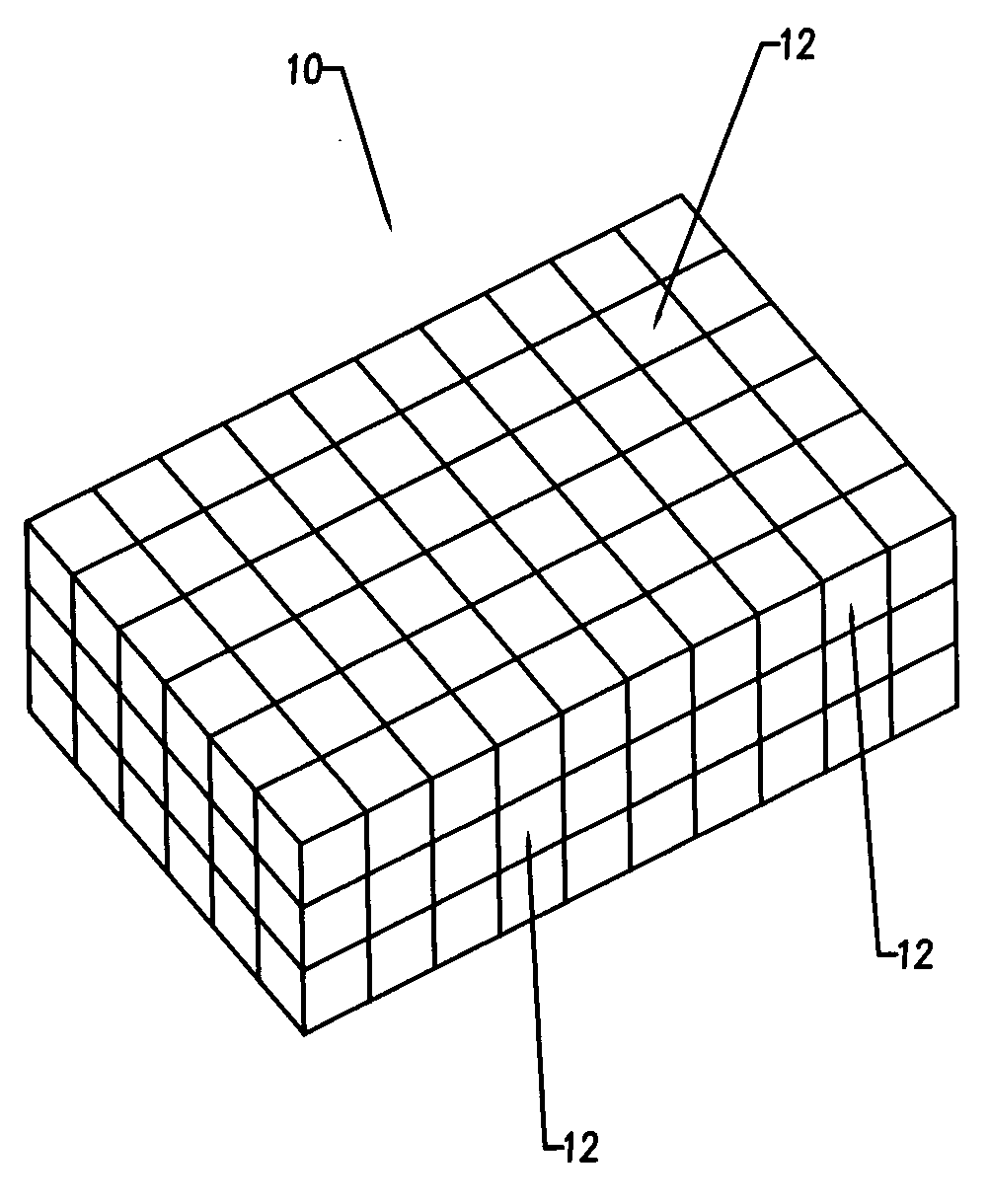
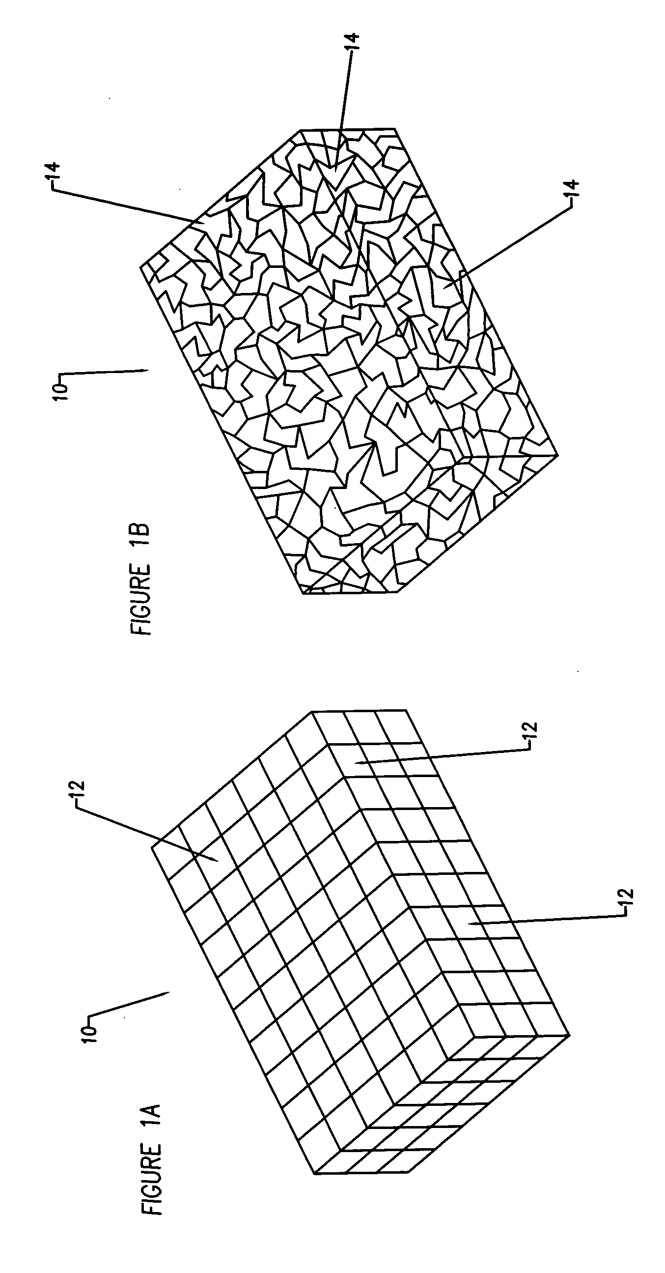
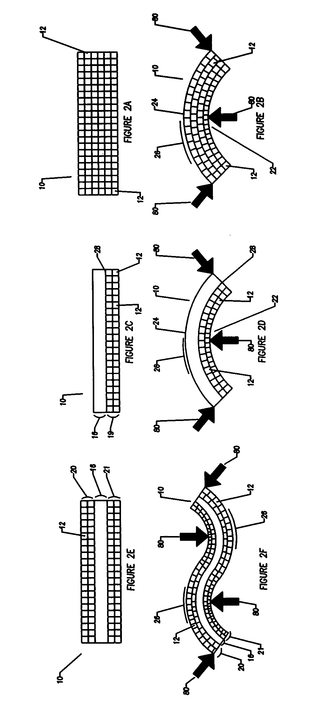
[0054] The object of the invention is an implantable prosthesis, constructed of a porous, resorbable, polymer material. The material comprising the prosthesis or device (as used herein, the terms prosthesis and device are used interchangeably) is a resorbable polymer that is biocompatible with the systems of a living being. The construction of the prosthesis is such that it is to be capable of easily being shaped. The shaping may occur in a variety of manners, such as by bending or compressing to conform to a desired shape without requiring any source of heating or special tools, and upon removal of the bending or shaping force, the prosthesis will remain in the exact shape, or nearly so; thus enabling the prosthesis to fit the unique contours of each patient. Despite being easily manipulated by hand, the prosthesis remains rigid and strong enough to lend structural support, and allows protection to the wound of a living being while the healing process occurs. The device has several...


PUM


Abstract

A bendable polymer tissue fixation device suitable to be implanted into a living body, comprising a highly porous body, the porous body comprising a polymer, the porous body comprising a plurality of pores, the porous body being capable of being smoothly bent, wherein the bending collapses a portion of the pores to form a radius curve, the polymer fixation device being rigid enough to protect a tissue from shifting. In a preferred embodiment the polymer fixation device may be capable of being gradually resorbed by said living body. In one embodiment, the polymer fixation device comprises a plurality of layers distinguishable by various characteristics, such as structural or chemical properties. In another embodiment, the polymer fixation device may comprise additional materials; the additional materials serving to reinforce or otherwise alter the structure or physical characteristics of the device, or alternatively as a method of delivering therapy or other agents to the system of a living being.

Description

FIELD OF THE INVENTION [0001] The invention generally relates to prosthetic implants, specifically relating to resorbable prosthetic implants. The invention more particularly concerns a resorbable osteosynthesis fixation plate. Specifically, an implant for joining tissue or bone fragments of the cranium, face and other plastic / reconstructive procedures. BACKGROUND OF THE INVENTION [0002] Rigid internal fixation has been indicated for treatment of defects of the mammalian skeletal system for decades. Although external fixation such as plaster and splints have been used to stabilize the skeleton since ancient times, it was not until the emergence of steel wire in the nineteenth century that a practical method for treating non-isolatable bone fragments such as those found in craniomaxillofacial repair situations was developed. [0003] A great advancement in skeletal fixation occurred in the late 1950s with the introduction of metallic plate systems. By securing the plate to the individu...

Claims


Application Information

Patent Timeline
IPC IPC(8): A61B17/00A61B17/80A61L31/04A61L31/12A61L31/14A61L31/16A61L31/18
CPCA61B17/80A61B2017/00004A61L31/04A61L31/125A61L31/146A61B17/8085A61L31/16A61L31/18A61L2300/00A61B17/8061A61L31/148
Inventor RINGEISEN, TIMOTHY A.
Owner DSM IP ASSETS BV
Why Eureka
Try Eureka