Plasma film forming system

a technology of plasma film and forming system, which is applied in the direction of coatings, chemical vapor deposition coatings, electric discharge tubes, etc., can solve the problems of increasing the number of parts, affecting the quality of plasma film, so as to reduce the frequency of maintenance and reduce the number of parts. , the effect of high quality film formation

Inactive Publication Date: 2005-01-27
SEKISUI CHEM CO LTD
View PDF11 Cites 50 Cited by
  • Summary
  • Abstract
  • Description
  • Claims
  • Application Information

AI Technical Summary

Benefits of technology

[0072] The support means preferably includes an intake duct having an intake port which is open downward and disposed in such a manner as to surround the processing head. Owing to this arrangement, the processed gas can be prevented from remaining in the space and discharged smoothly. Eventually, stain adhered to the base material opposing member can be reduced, and the frequency of maintenance can be reduced. Moreover, since the support means and the intake duct are composed of a common member, the number of parts can be reduced.
[0073] In the first feature, it is preferable that the processing head includes a member to be faced with the base material, the base material opposing member includes a blowoff region where the first and second gas blowoff passages are disposed and an expanding region expanded from the blowoff region thereby to gain a ratio for forming a film, and the expanding region is connected with an inert gas introduction means; and the expanding region of the base material opposing member is composed of a material having such a degree of gas permeability that the inert gas coming from the gas introduction means is allowed to permeate toward a base material opposing surface and the degree of permeation and thus the degree of oozing of the inert gas from the base material opposing surface is such that the processing gas can be prevented from contacting the base material opposing surface without disturbing a flow of the processing gas (see FIG. 34). Owing to this arrangement, a thin layer of inert gas can be formed on the base material opposing surface, particularly on the expanding region, so that film can surely be prevented from adhering to the base material opposing surface. In addition, a film can sufficiently be formed while guiding the processing gas to the expanding region without disturbing the processing gas flow in the space between the processing head and the base material.
[0074] The gas permeating material is preferably a porous material. Owing to this arrangement, the desired degree of permeation and thus oozing-out can be obtained easily and reliably. Particularly, by composing the gas permeating material from a porous material, an insulative property can surely be obtained, too.
[0075] It is preferable that a groove for temporarily storing therein the inert gas coming from the gas introduction means is formed in an opposite side surface to the base material opposing surface in the expanding region of the base material opposing member in such a manner as to be recessed toward the base material opposing surface. Owing to this arrangement, the base material opposing member in the expanding region can be reduced in thickness, and an inert gas film can surely be formed on the base material opposing surface, thereby a film can be prevented from being adhered to this surface more reliably.
[0076] It is preferable that the base material opposing member has a short direction and a longitudinal direction, each of the regions extends in the longitudinal direction, the expanding region is provided at both sides in the short direction with the blowoff region sandwiched therebetween, and the groove is formed in each expanding direction in such a manner as to extend in the longitudinal direction. Owing to this arrangement, a film can efficiently be formed over a wide range of area at a time, and a film can surely be prevented from adhering to the two expanding regions.
[0077] It is preferable that the base material opposing member is entirely integrally formed from a gas permeating material, and a gas permeation prohibiting member for prohibiting gas permeation is disposed at an inner side surface facing with the blowoff region of the groove. Owing to this arrangement, the processing gas flow can surely be prevented from being disturbed or diluted in the blowoff region by inert gas, and therefore, a high quality film formation can be enjoyed.

Problems solved by technology

However, this film formation processing technique has such a problem that the film, which is originally intended to be adhered to the base material, is liable to adhere to the apparatus side.
This results in loss of an increased amount of raw material.
Total replacement of the main component such as electrodes means significant waste of the component materials.
Moreover, it is extremely troublesome to totally clean the nozzle in order to remove the adhesion (stain) adhered to the peripheral area of the blowoff passage.
This techniques, however, again has such a problem that the flow of processing gas is disturbed by the inert gas coming through the meshes, thus badly degrading the film formation efficiency onto the base material.
Moreover, the normal pressure plasma surface processing has such a problem that an average free travel (life span) of the radicals is short compared with the lower pressure circumstance.
For this reason, if the nozzle is arranged too away from the base material, it becomes unable to form a film due to deactivation.
On the other hand, if the nozzle is arranged too close to the base material, arc is liable to occur between the electrode on the side to which the electric field is impressed and the base material, and the base material gets, in some instances, damaged.

Method used


Image

  • Plasma film forming system
  • Plasma film forming system
  • Plasma film forming system

Examples


first embodiment

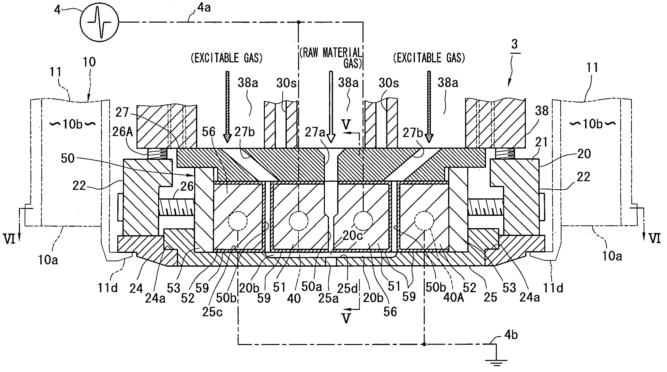
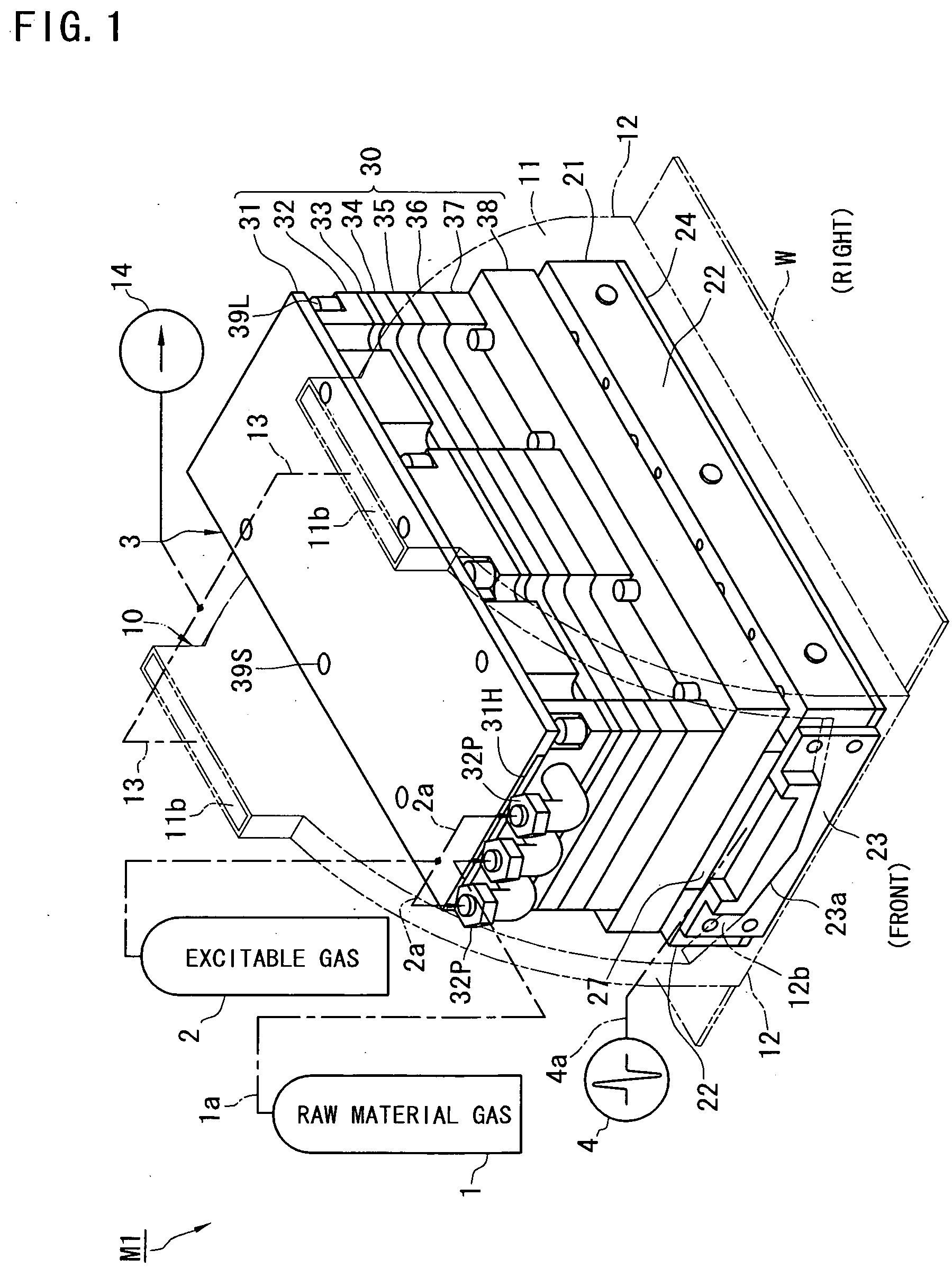
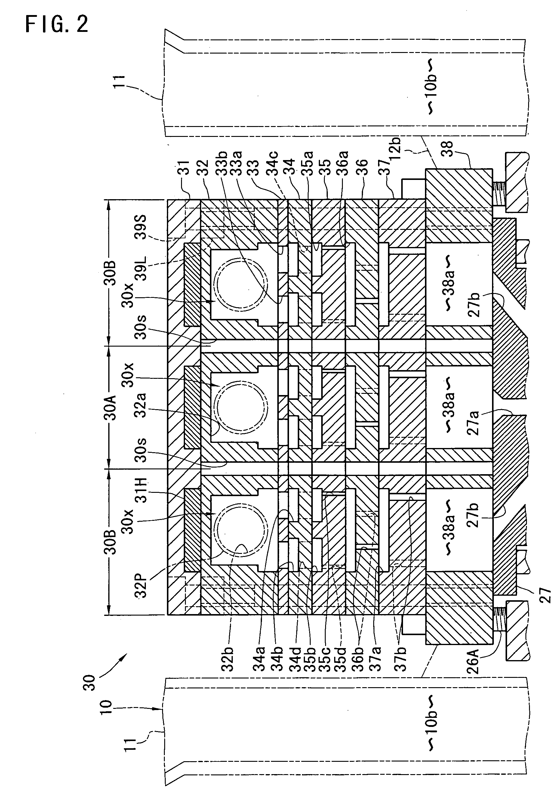
[0126]FIG. 1 shows a normal pressure plasma film forming apparatus M1 according to the present invention. The normal pressure plasma film forming apparatus M1 comprises a frame (support means) including a housing 10, a processing head 3 supported on the housing 10 of the frame, two kinds of processing gas sources 1, 2 connected to the processing head 3, and a power source 4. Beneath the processing head 3, a plate-like base material W (material to be processed) having a large area is transferred in the left and right direction by transfer means (not shown) It is, of course, accepted that the base material W is fixed and the processing head 3 is moved. In the normal pressure plasma film forming apparatus M1, a film A (FIG. 8) such as, for example, amorphous silicon (a-Si) and silicon nitride is formed on an upper surface of this base material W.

[0127] Of the two kinds of processing gas sources, a raw material gas source 1 (first gas source) stores therein a raw material gas (first gas...

third embodiment

[0198]FIG. 13 shows the present invention.

[0199] In the third embodiment, an electrode group consisting of eight (a plurality of) planar electrodes 51, 52 is disposed within a metal conductor-made nozzle body 20B of a processing head 3. Those electrodes are in mutually parallel relation and arranged at equal intervals in the order of the ground electrode 52, the electric field impressing electrode 51, the ground electrode 52, the ground electrode 52, the electric field impressing electrode 51, the electric field impressing electrode 51 and the ground electrode 52 from left. Owing to this arrangement, the second flow passages (plasma discharge space) 50b between the electrodes having different polarities and the first flow passages 50a between the electrodes having the same polarities are alternately arranged. Each first flow passage 50a allows the raw material gas (first gas) from a raw material gas source (not shown) to pass therethrough, and each second flow passage 50b allows the...

fourth embodiment

[0206]FIGS. 15 through 20 show the present invention.

[0207] In the fourth embodiment, as in the first embodiment, second flow passages are arranged on the left and right sides with a central first flow passage sandwiched therebetween. Those three flow passages are converged and continuous with a single common blowoff passage 25a. The fourth embodiment is different from the first embodiment in respect of the arrangement position of the ground electrode and the location of the plasma discharge part of the second flow passage.

[0208] More specifically, as shown in FIGS. 15 and 17, in the processing head 3 of the fourth embodiment, dummy electrode spacers 52S instead of the ground electrodes 52 of the first embodiment are disposed at the locations for receiving the ground electrodes 52 of the first embodiment (FIGS. 3 and 6). The dummy electrode spacers 52S each have a substantially same configuration as the ground electrodes 52 of the first embodiment, but they are composed of an insul...


PUM

PropertyMeasurementUnit
pressureaaaaaaaaaa
frequencyaaaaaaaaaa
electric field strengthaaaaaaaaaa

Abstract

In a plasma film forming apparatus, two first electrodes 51 connected to a power source 4 and two grounded second electrodes 52 are arranged in the order of the second electrode 52, the first electrode 51, the first electrode 51 and the second electrode 52. A first flow passage 50a formed between the central first electrodes 51 allows a raw material gas (first gas) for being formed into a film to pass therethrough. A plasma discharge space 50b of a second flow passage formed between the first and second electrodes 51, 52 on the both sides allows an excitable gas (second gas) to pass therethrough, which excitable gas is exited by plasma such that the raw material can be formed into a film, but that the excitable gas itself is merely excited but not formed into a film. Those gases are converged at a crossing part 20c between the first and second flow passages and blown off via a common blowoff passage 25a. By this, the apparatus composing members such as electrodes can be prevented from being adhered with a film.

Description

TECHNICAL FIELD [0001] This invention relates to a plasma surface processing technique, in which a processing gas is plasmatized by impressing an electric field between a pair of electrodes, processing such as film formation, etching, ashing, cleaning, surface modification or the like is executed with respect to the surface of a base material of a semiconductor base material or the like. More particularly, the invention relates to an apparatus suited for the so-called remote-control type in which a base material is arranged away from an electric field impressing space between electrodes of a base material, in a plasma film forming apparatus. BACKGROUND ART [0002] The plasma surface processing apparatus is provided with a pair of electrodes (for example, Japanese Patent Application Laid-Open No. H11-236676). A processing gas is introduced between the pair of electrodes and an electric field is also impressed therebetween to generate a glow discharge. By this, the processing gas is pl...

Claims


Application Information

Patent Timeline
Patent Type & Authority Applications(United States)
IPC IPC(8): C23C16/44C23C16/452C23C16/455C23C16/509H01J37/32
CPCC23C16/452C23C16/45514C23C16/45563H01J37/3244C23C16/45595C23C16/509C23C16/45574
Inventor KAWASAKI, SHINICHINAKATAKE, SUMIOKITAHATA, HIROYANAKAJIMA, SETSUOEGUCHI, YUJIANZAI, JUNICHIRONAKANO, YOSHINORI
Owner SEKISUI CHEM CO LTD
Why Eureka
Try Eureka