Measurements of optical inhomogeneity and other properties in substances using propagation modes of light

a propagation mode and substance technology, applied in the field of noninvasive, optical probing of various substances, can solve the problems of significant fluctuation and drift of the separation of the reference light beam from the sample light beam, and the relative optical phase or differential delay between the two beams may experience uncontrolled fluctuations and variations, and achieve effective use of source radiation, high signal stability, and high signal-to-noise ratio

Active Publication Date: 2005-01-27
SAMSUNG ELECTRONICS CO LTD
View PDF14 Cites 42 Cited by
  • Summary
  • Abstract
  • Description
  • Claims
  • Application Information

AI Technical Summary

Benefits of technology

Exemplary implementations are described below to illustrate various features and advantages of the systems and techniques. One of such features is methods and apparatus for acquiring information regarding optical inhomogeneity in substance by a non-invasive means with the help of a low-coherence radiation. Another feature is to achieve high signal stability and high signal-to-noise ratio by eliminating the need of splitting the light radiation into a sample path and a reference path. Additional features include, for example, a platform on which phase-resolved measurements such as birefringence and absolute refractive indices can be made, capability of acquiring optical inhomogeneity with regard to the spectral absorbance, solving the problem of signal drifting and fading caused by the polarization variation in various interferometer-based optical systems, and an effective use of the source radiation with simple optical arrangements. Advantages of the systems and techniques described here include, among others, enhanced performance and apparatus reliability, simplified operation and maintenance, simplified optical layout, reduced apparatus complexity, reduced manufacturing complexity and cost.

Problems solved by technology

As an example, at least one of disadvantages associated to the OCDR system designs shown in FIG. 1 or described in the aforementioned patents is the separation of the reference light beam from the sample light beam.
Due to the separation of the optical paths, the relative optical phase or differential delay between the two beams may experience uncontrolled fluctuations and variations, such as different physical length, vibration, temperature, waveguide bending and so on.
When the sample arm is in the form of a fiber-based catheter that is separate from the reference arm, for example, the manipulation of the fiber may cause a significant fluctuation and drift of the differential phase between the sample and reference light beams.
This fluctuation and draft may adversely affect the measurements.
For example, the fluctuation and drift in the differential phase between the two beams may lead to technical difficulties in phase sensitive measurements as absolute valuation of refractive indices and measurements of birefringence.
In some OCDR systems such as systems in aforementioned patents, it may be difficult to perform direct measurements of the optical inhomogeneity with regard to these and other spectral characteristics.

Method used


Image

  • Measurements of optical inhomogeneity and other properties in substances using propagation modes of light
  • Measurements of optical inhomogeneity and other properties in substances using propagation modes of light
  • Measurements of optical inhomogeneity and other properties in substances using propagation modes of light

Examples


Embodiment Construction

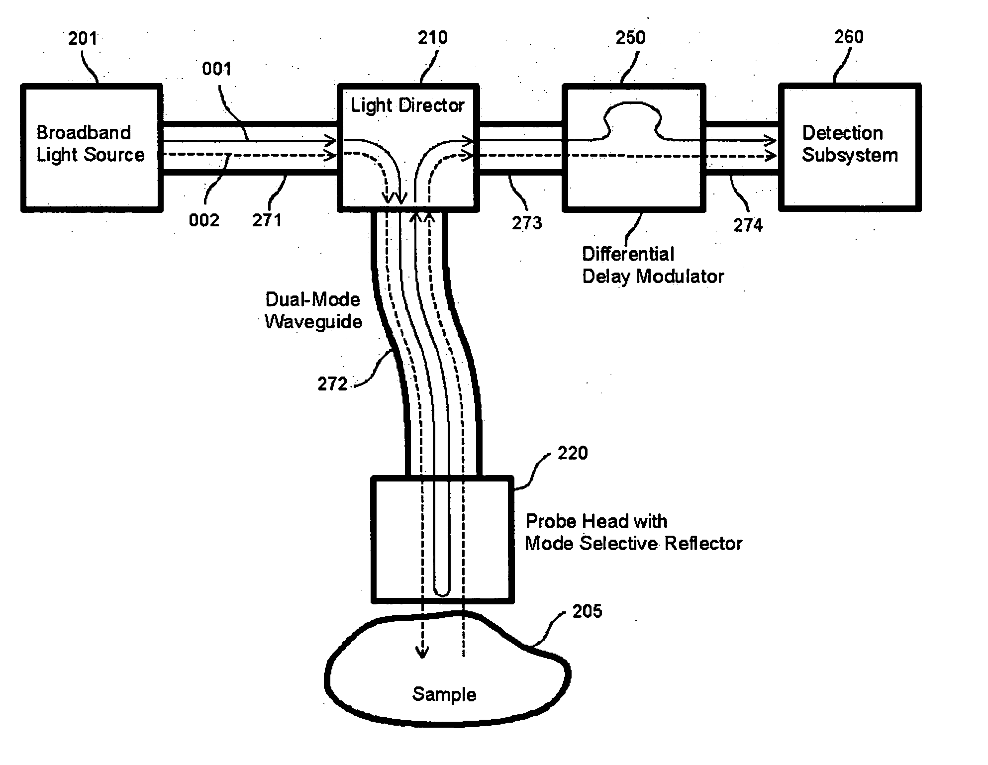
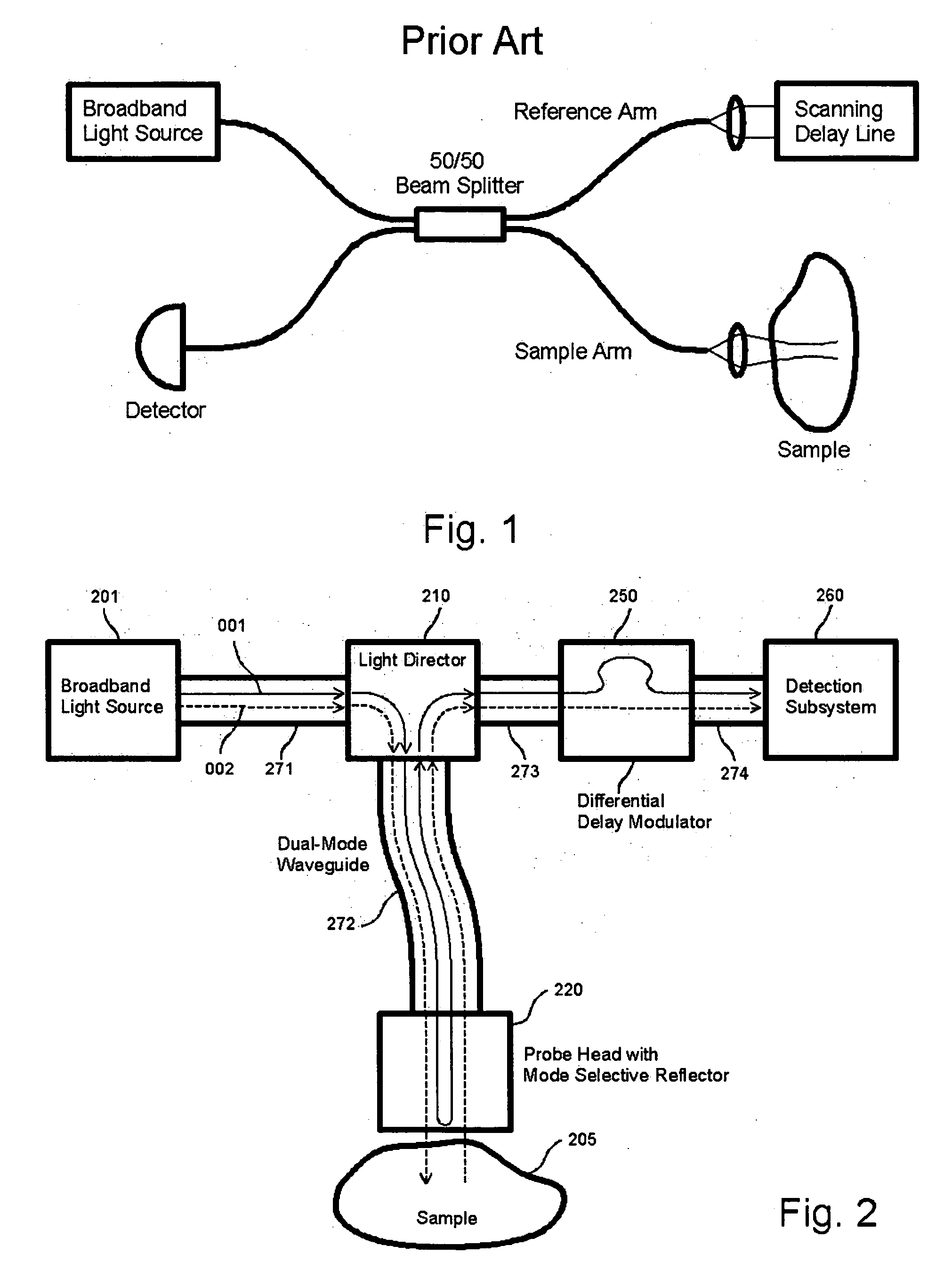
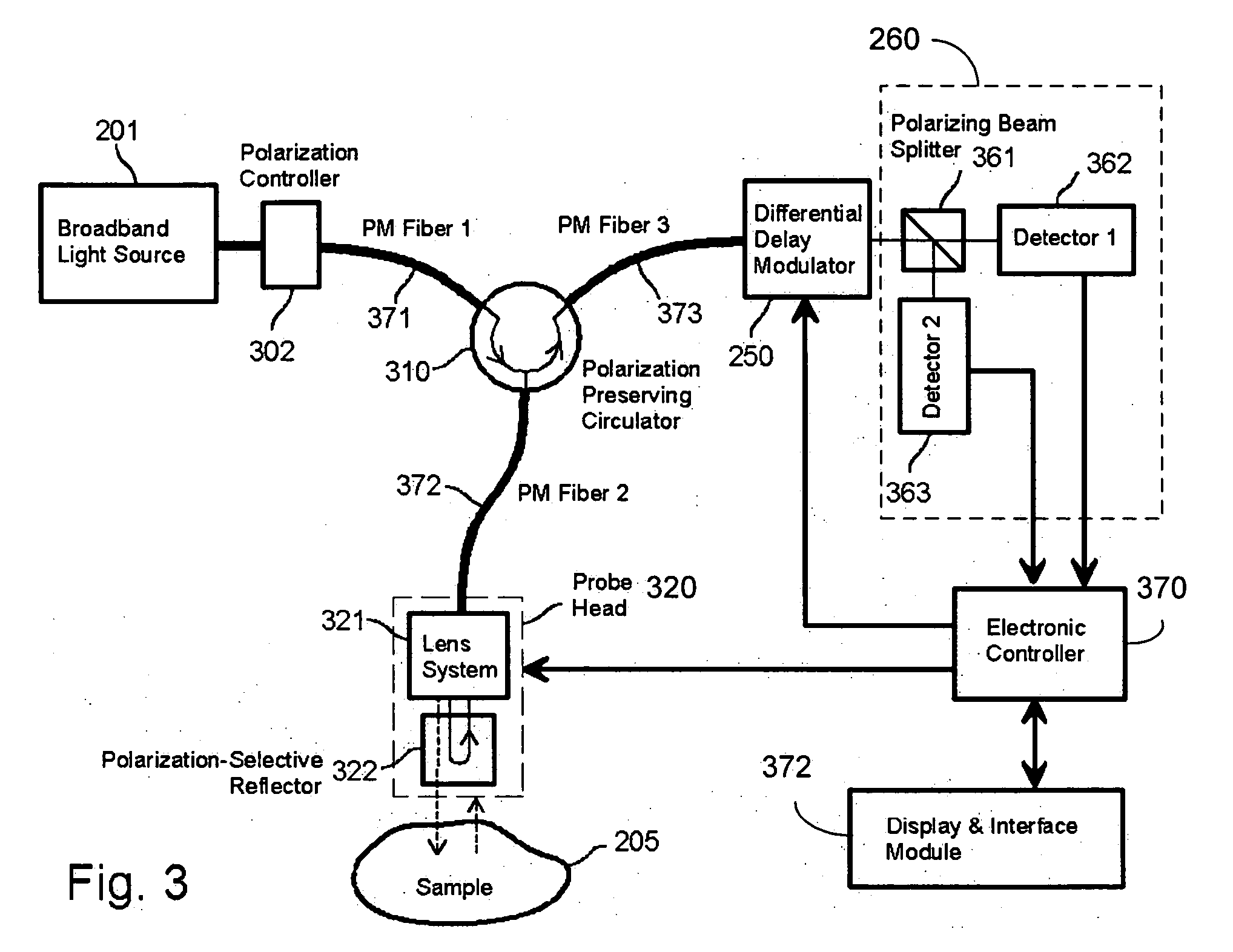
Energy in light traveling in an optical path such as an optical waveguide may be in different propagation modes. Different propagation modes may be in various forms. States of optical polarization of light are examples of such propagation modes. Two independent propagation modes do not mix with one another in the absence of a coupling mechanism. As an example, two orthogonally polarization modes do not interact with each other even though the two modes propagate along the same optical path or waveguide and are spatially overlap with each other. The exemplary techniques and devices described in this application use two independent propagation modes in light in the same optical path or waveguide to measure optical properties of a sample. A probe head may be used to direct the light to the sample, either in two propagation modes or in a single propagation modes, and receive the reflected or back-scattered light from the sample.

For example, one beam of guided light in a first propaga...


PUM

PropertyMeasurementUnit
wavelengthaaaaaaaaaa
relative phase delayaaaaaaaaaa

Abstract

This application describes designs, implementations, and techniques for controlling propagation mode or modes of light in a common optical path, which may include one or more waveguides, to sense a sample.

Description

BACKGROUND This application relates to non-invasive, optical probing of various substances, including but not limited to, skins, body tissues and organs of humans and animals. Investigation of substances by non-invasive and optical means has been the object of many studies as inhomogeneity of light-matter interactions in substances can reveal their structural, compositional, physiological and biological information. Various devices and techniques based on optical coherence domain reflectometry (OCDR) may be used for non-invasive optical probing of various substances, including but not limited to skins, body tissues and organs of humans and animals, to provide tomographic measurements of these substances. In many OCDR systems, the light from a light source is split into a sampling beam and a reference beam which propagate in two separate optical paths, respectively. The light source may be partially coherent source. The sampling beam is directed along its own optical path to impin...

Claims


Application Information

Patent Timeline
Patent Type & Authority Applications(United States)
IPC IPC(8): A61B5/00G01B9/02G01J3/02G01J3/42G01N21/21G01N21/47G01N21/49G02B21/06
CPCA61B5/0059G01B2290/35A61B5/0073A61B5/14532A61B5/1455A61B5/14558A61B2562/0242G01J3/02G01J3/021G01J3/0218G01J3/0224G01J3/42G01N21/21G01N21/474G01N21/4795G01N21/49G01N2021/4709G01N2021/4792G02B21/06G01N21/27G01N21/55G01B9/0201G01B9/02044G01B9/02057G01B9/02091G01B2290/70G01B2290/40G01B2290/45A61B5/0066
Inventor WANG, FEILING
Owner SAMSUNG ELECTRONICS CO LTD
Why Eureka
Try Eureka