Optical connector assembly

a technology of optical connectors and connectors, applied in the field of optical connector assemblies, can solve the problems of reducing alignment tolerance, complicated alignment procedures of these types of assemblies, and more conventional packaging, so as to facilitate coupling procedures, overcome slight misalignments of optical fibers, and maximize coupling efficiency

Active Publication Date: 2005-01-27
REFLEX PHOTONIQUE REFLEX PHOTONICS
View PDF4 Cites 37 Cited by
  • Summary
  • Abstract
  • Description
  • Claims
  • Application Information

AI Technical Summary

Benefits of technology

[0014] This invention relates to the optical coupling of light emitted, absorbed or altered by optoelectronic devices (such as photodetectors, light emitting diodes, lasers, vertical cavity surface emitting lasers (VCSEL), etc.) with optical waveguides (such as optical fibers, planar waveguides, etc.). The invention facilitates the coupling procedure by using mechanical assemblies to hold the waveguides in contact with the optoelectronic devices. These assemblies do not require any other coupling agent, such as lenses, but must be sufficiently close in order to maximize the coupling efficiency into (or out of) the waveguide (optical fiber). Both assemblies are particularly amenable to a one-step alignment process involving the planar-on-planar (or stacked) 2-D alignment of the waveguide assembly with an optoelectronic assembly. The assemblies are stacked on top of each other and viewed from above to simultaneously observe features on both the waveguide assembly and the optoelectronic assembly. The alignment process involves sliding the two assemblies (waveguide assembly and optoelectronic assembly) with respect to each other on their co-incident 2-D surfaces. This procedure can be done passively (without energizing the optoelectronic assembly), and requires only one alignment step to be performed. This is contrary to other methods described in the prior art that use mechanical constraints, such as extra grooves, stop-walls, stand-offs, precision machining or precise pick-and-place methods to align waveguides to optoelectronic devices. It also supercedes older methods that rely on large optoelectronic devices to overcome slight misalignments of the optical fiber.

Problems solved by technology

This method allows more conventional packaging and reduces the alignment tolerance because the length of the optical fiber is essentially laid over the flat surface of the PCB.
The alignment procedures for these types of assemblies are complicated.
These methods typically involve micro-solder ball re-flow, flip-chip alignment and / or precisely machined parts, which require significant resources and materials.
This technique may be adequate for large area optoelectronics, but would not be a suitable alignment methodology for small devices such as VCSELs.
This completely rules-out a VCSEL chip since the vertical cavity laser would be damaged if bonded up-side-down, not to mention that the wirebond connections are made on the same surface as the vertical cavity laser and it would be physically impossible to wirebond to the VCSEL chip in such an orientation.

Method used


Image

  • Optical connector assembly
  • Optical connector assembly
  • Optical connector assembly

Examples


Embodiment Construction

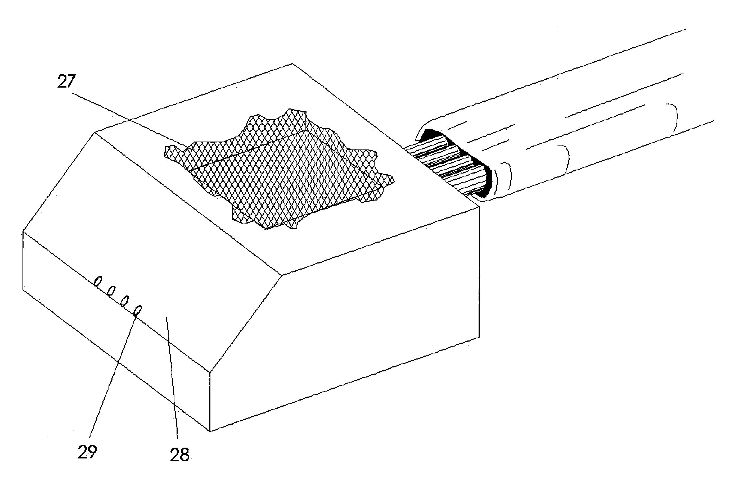
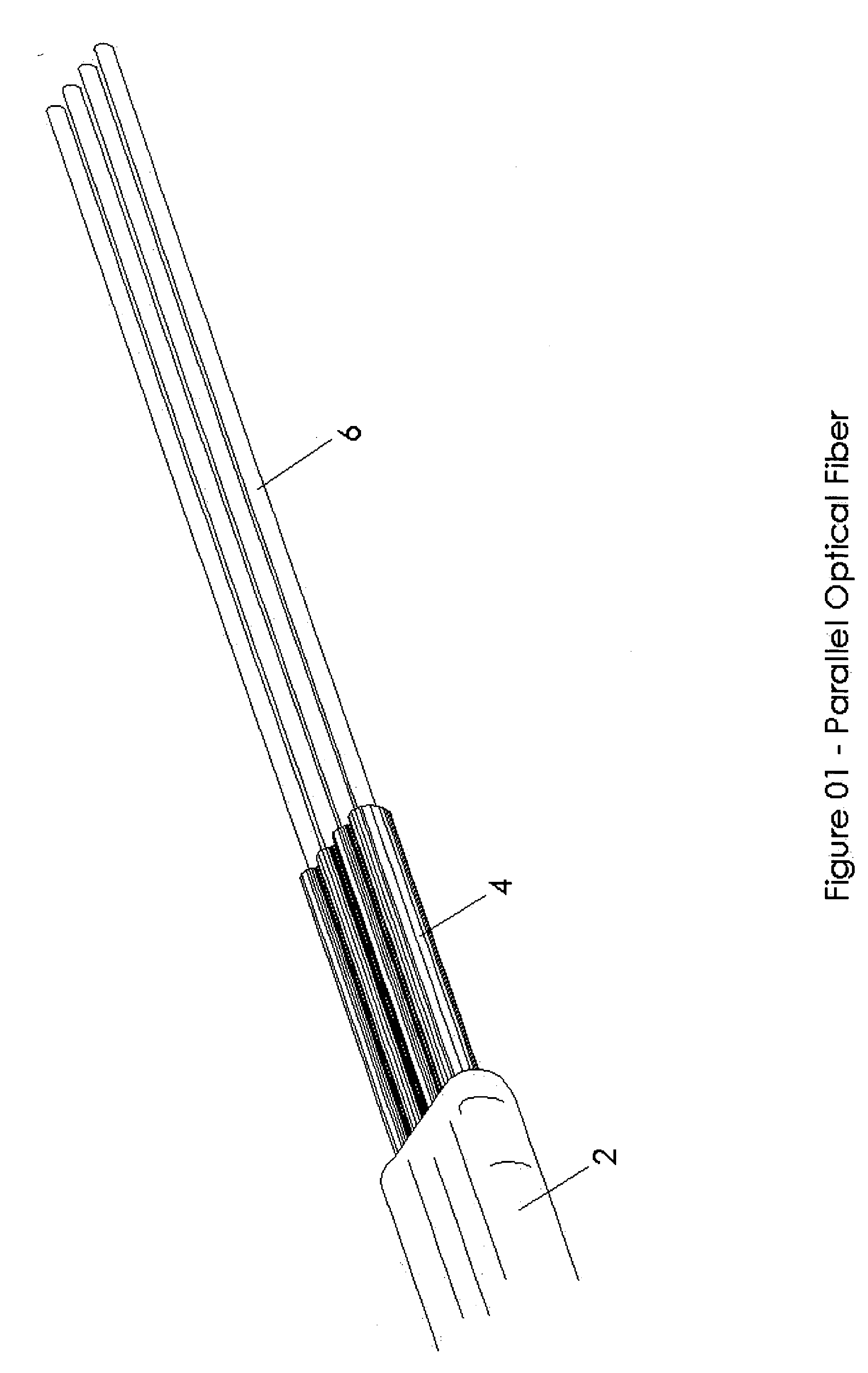
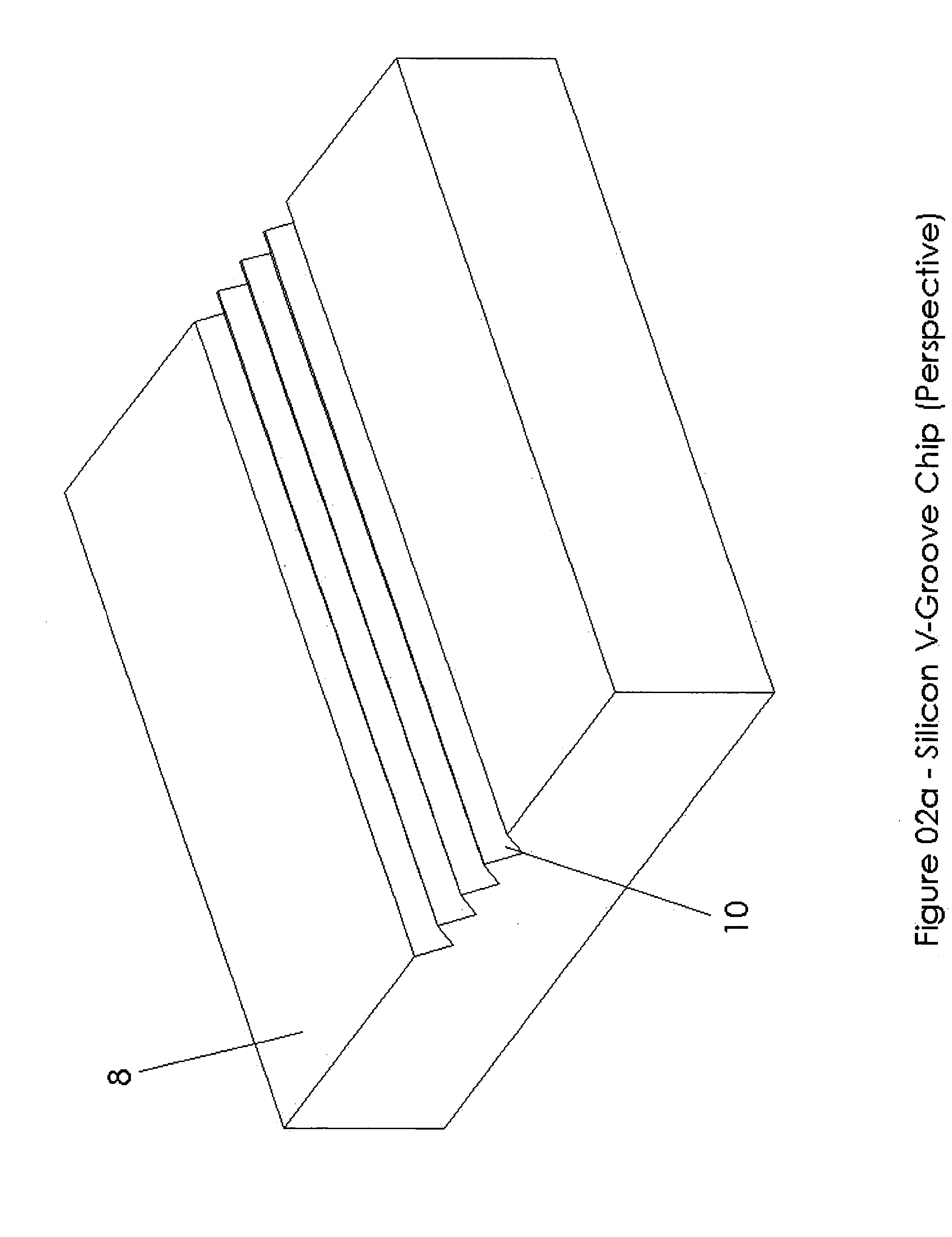
[0046] The parallel optical connector is a mechanical structure used to connect a parallel optical fiber ribbon to an array of optoelectronic devices, such as a vertical cavity surface emitting laser (VCSEL), or photodetector array.

[0047] The parallel optical connector consists of a structure to rigidly hold optical fibers in the same plane and pitched from each other at 250-microns. One end of the structure is polished at a 45-degree angle to create a reflective glass-air interface at the fiber tips. This interface can reflect light at 90-degrees by either total internal reflection (TIR) when the glass-air interface is preserved, or by depositing a reflective metal layer on the exposed tips of the fiber. The reflective metal layer may be made of gold, silver, etc.

[0048] Light directed at the 45-degree tips of the optical fiber will be reflected and coupled into the optical fiber orthogonal to the initial direction. In this situation, light will pass though the side of the optical...


PUM


Abstract

A method and apparatus is disclosed for enabling a coupling of at least one optical fiber with an optoelectronic device. The apparatus comprises at least one v-groove for receiving at least one optical fiber. A first end of the apparatus is then polished at a predetermined angle in order to enable an optical coupling with the optoelectronic device.

Description

CROSS-REFERENCE TO RELATED APPLICATIONS [0001] This is the first application filed for the present invention. This application is related to commonly assigned co-pending applications filed herewith bearing agent docket numbers 16005-2US entitled “Optical Ferrule” and 16005-3US entitled “Encapsulated Optical Package”, the specifications of which are hereby incorporated by reference. TECHNICAL FIELD [0002] This invention relates to the field of optical connecting devices. More precisely, this invention relates to methods and apparatus for connecting optical fibers to optoelectronic devices. BACKGROUND OF THE INVENTION [0003] The optical coupling of light emitted, absorbed or altered by optoelectronic (OE) devices, such as photodetectors, light emitting diodes (LED's), lasers, and vertical cavity surface emitting lasers (VCSEL), with optical waveguides, such as optical fibers and planar waveguides, is well known in conventional photonics. One technique that is known involves cutting an...

Claims


Application Information

Patent Timeline
Patent Type & Authority Applications(United States)
IPC IPC(8): G02B6/42
CPCG02B6/4204G02B6/4249G02B6/4221G02B6/4214
Inventor ROLSTON, DAVID ROBERT CAMERONMAJ, TOMASZ
Owner REFLEX PHOTONIQUE REFLEX PHOTONICS
Why Eureka
Try Eureka