FCC spent catalyst distributor

a distributor and catalyst technology, applied in the direction of physical/chemical process catalysts, furnaces, lighting and heating apparatus, etc., can solve the problems of high oxygen concentration localized areas, bubbling bed regenerators, and more severe problems, so as to simplify the reduction or elimination of non-uniformities

Inactive Publication Date: 2005-01-27
UOP LLC
View PDF38 Cites 57 Cited by
  • Summary
  • Abstract
  • Description
  • Claims
  • Application Information

AI Technical Summary

Benefits of technology

[0020] It is an object of this invention to provide a method and apparatus that simplifies the reducing or

Problems solved by technology

Although all FCC regenerators produce some NOx, the problem is more severe in bubbling bed regenerators, as opposed to high efficiency regenerators.
Bubbling bed regenerators may have poorly fluidized regions and will have large bubbles of air passing through the bed, leading to localized areas of high oxygen concentration.
Unfortunately, the catalysts used in these processes are readily fouled, or the process equipment plugged, by catalyst fines that are an integral part of FCC regenerator flue gas.
Flue gas treatment methods are effective, but the capital and operating costs are high.
First, some refiners now go to the expense of hydrotreating feed.
Again, there is typically a high cost for this procedure and it c

Method used


Image

  • FCC spent catalyst distributor
  • FCC spent catalyst distributor
  • FCC spent catalyst distributor

Examples


Embodiment Construction

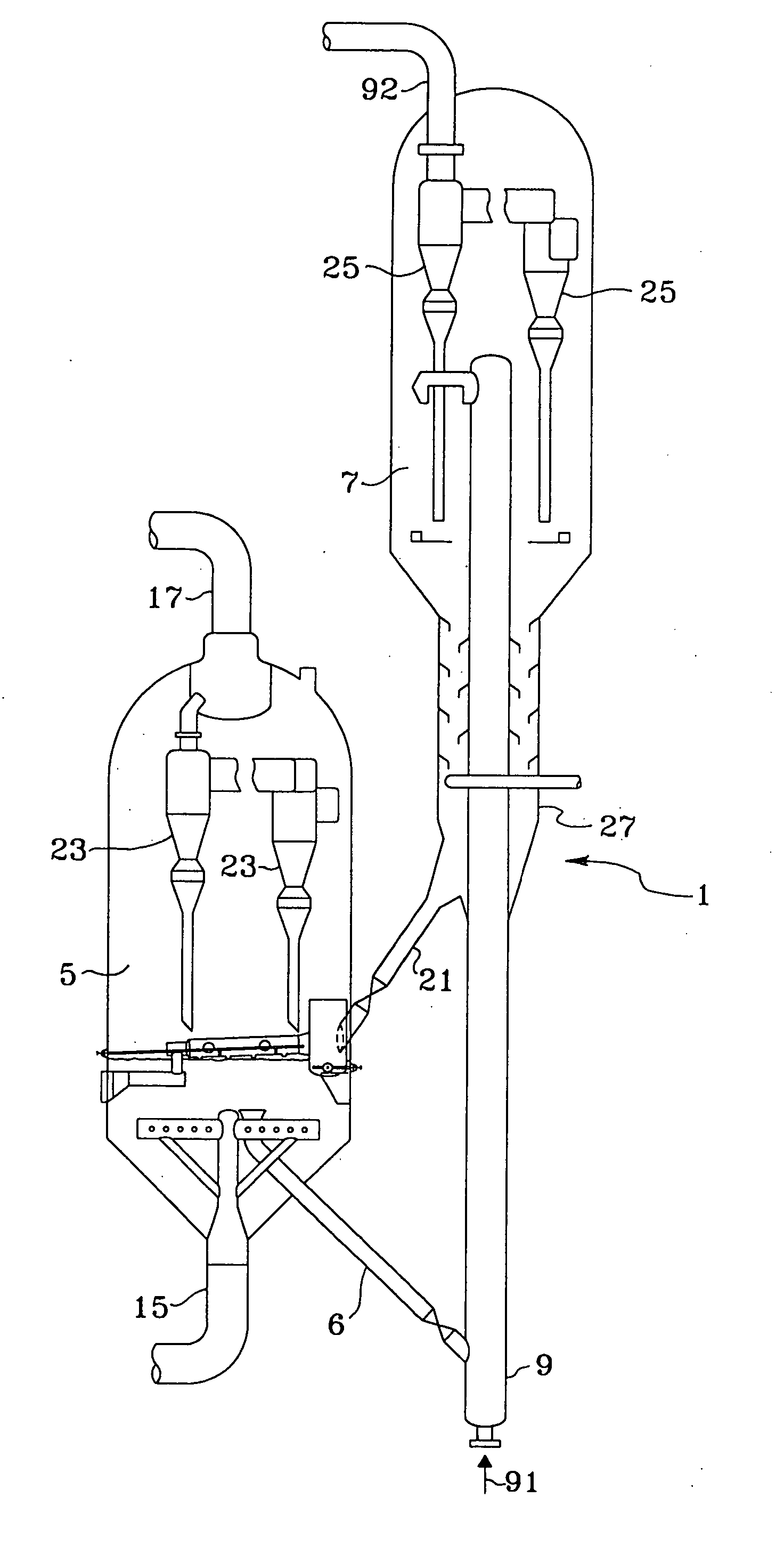
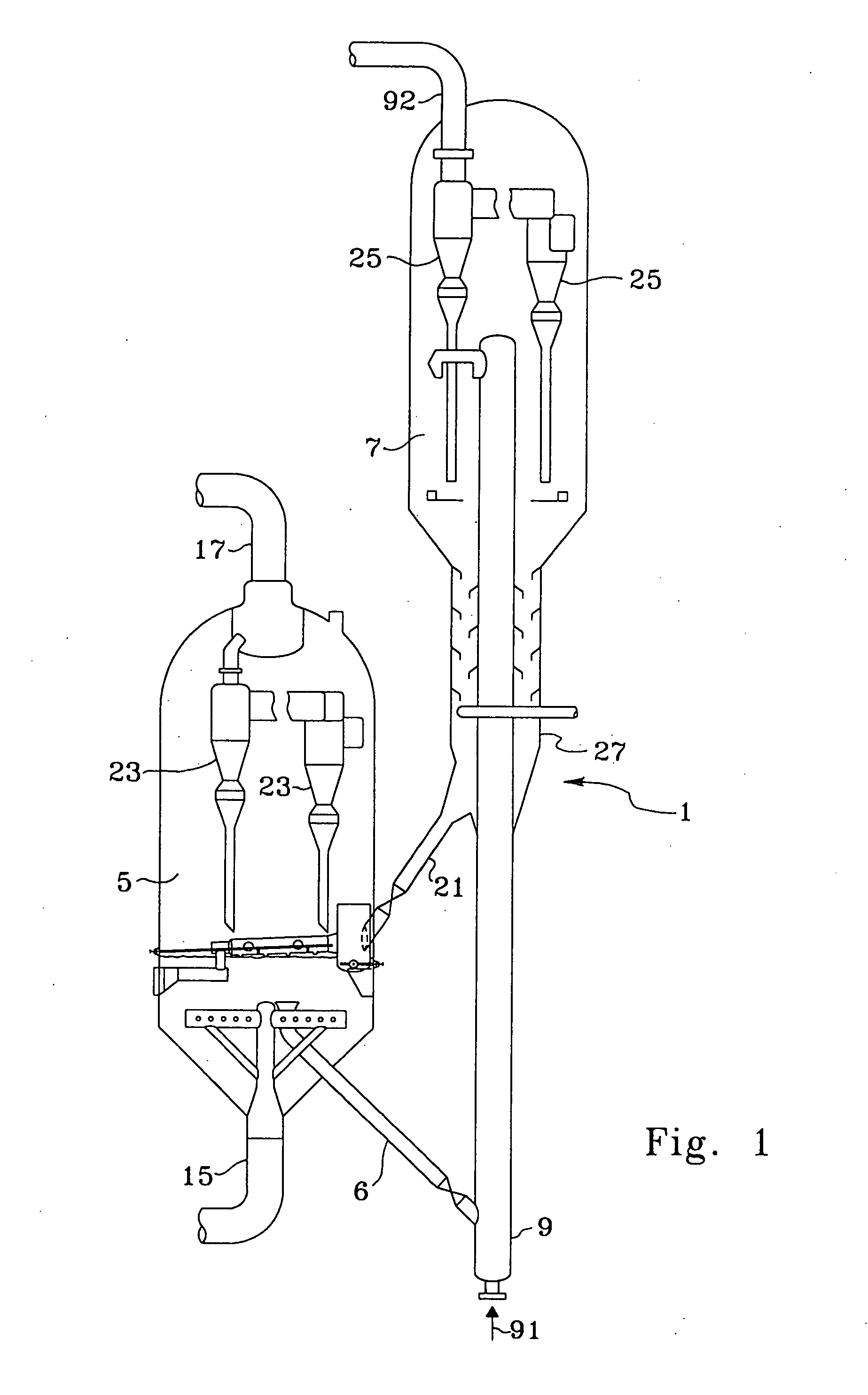
[0034] An FCC process unit, generally referred to with reference numeral 1 and shown schematically in FIG. 1, generally comprises two main zones for reaction and regeneration. A reaction zone is usually comprised of a vertical conduit, or riser 9, as the main reaction site, with the effluent of the conduit emptying into a large volume process vessel, which may be referred to as a separation vessel 7. In the reaction zone, a feed stream 91 is contacted with a finely divided fluidized catalyst at an elevated temperature and at a moderate positive pressure. The feed stream 91 to the FCC unit consists of a mixture of hydrocarbons having boiling points above about 232° C. In the riser, feed is contacted with a relatively large fluidized bed of catalyst. The residence time of catalyst and hydrocarbons in the riser needed for substantial completion of the cracking reactions is only a few seconds. The flowing vapor / catalyst stream leaving the riser 9 passes from the riser to a solids-vapor ...


PUM

PropertyMeasurementUnit
Angleaaaaaaaaaa
Angleaaaaaaaaaa
Flow rateaaaaaaaaaa

Abstract

An distributor arrangement introduces spent FCC catalyst more uniformly across the dense bed of the regenerator to provide more even contact with regeneration gas in order to avoid hot spots and zones of incomplete combustion. The invention forms a fluidized hopper to collect spent catalyst and a horizontally extended header with multiple horizontally extended outlet arms to place catalyst into the regenerator. The invention may use an aeration means to fluidize the header to further assist catalyst flow. Furthermore, the spent catalyst delivered to the top of the regenerator dense reduces NOx emissions in the flue gas.

Description

CROSS-REFERENCE TO RELATED APPLICATION [0001] This application is a Division of copending application Ser. No. 09 / 717,741 filed Nov. 21, 2000, the contents of which are hereby incorporated by reference in its entirety.BACKGROUND OF THE INVENTION [0002] This invention relates generally to the dispersing of fluidized solids into a vessel. More specifically, this invention relates to a method and apparatus for distributing a stream of spent fluidized cracking catalyst particles into a regenerator for carbon removal. DESCRIPTION OF THE PRIOR ART [0003] There are a number of continuous cyclical processes employing fluidized solid techniques in which carbonaceous materials are deposited on the solids in a contacting zone and the solids are conveyed during the course of the cycle to another zone where carbon deposits are at least partially removed by combustion in an oxygen-containing medium. The solids from the latter zone are subsequently withdrawn and reintroduced in whole or in part to...

Claims


Application Information

Patent Timeline
IPC IPC(8): B01J38/30C10G11/18
CPCB01J38/30C10G11/182
Inventor MYERS, DANIELTRETYAK, MIKHAILPITTMAN, RUSTYNIEWIEDZIAL, STEVEN
Owner UOP LLC
Why Eureka
Try Eureka