Eureka AIR delivers breakthrough ideas for toughest innovation challenges, trusted by R&D personnel around the world.

Information recording medium and method for producing the same

a technology of information recording medium and information recording layer, which is applied in the direction of photosensitive materials, instruments, photomechanical equipment, etc., can solve the problems of increasing the temperature of the dielectric layer, reducing the light absorption of the recording layer, and requiring low thermal conductivity and transparency. , to achieve the effect of low thermal conductivity, good recording sensitivity and high transparency

Active Publication Date: 2005-01-27
PANASONIC CORP
View PDF13 Cites 37 Cited by
  • Summary
  • Abstract
  • Description
  • Claims
  • Application Information

AI Technical Summary

Benefits of technology

[0013] Therefore, with the foregoing in mind, it is an object of the present invention to provide a dielectric material having low thermal conductivity and high transparency, and to provide an information recording medium having good recording sensitivity while maintaining the conventional repeated rewriting performance and moisture resistance by employing this dielectric material.

Problems solved by technology

Materials containing S are not suitable.
However, low thermal conductivity and transparency also are required for a material suitable for forming an interface layer or a dielectric layer.
If the material is not transparent, the dielectric layer absorbs light, which reduces light absorption of the recording layer and increases the temperature of the dielectric layer.
When the temperature of the dielectric layer is increased, this makes it difficult to cool the recording layer rapidly and form satisfactory amorphous marks during recording.
As a result, the signal quality is deteriorated.
Thus, the rapid cooling effect is small and a large laser power is necessary to form amorphous marks (low recording sensitivity).
Thus, ZrO2—SiO2—Cr2O3 has problems in thermal conductivity and transparency.

Method used


Image

  • Information recording medium and method for producing the same
  • Information recording medium and method for producing the same
  • Information recording medium and method for producing the same

Examples


examples

[0268] Next, the present invention will be described more specifically by way of examples.

[0269] Test 1

[0270] The relationship between the nominal composition (in other words, the composition indicated nominally by a sputtering target manufacturer when being supplied) of the sputtering target made of an oxide-based material used in the production of the information recording medium of the present invention and the analyzed composition was confirmed by a test.

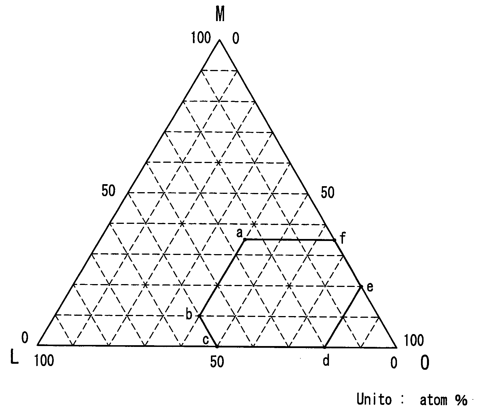
[0271] In this test, the sputtering target indicated as (ZrO2)25(SiO2)25(Ga2O3)50 (mol %) corresponding to the formula (19) as the nominal composition was made into powder, and the composition was analyzed by the X-ray microanalyzer method. As a result, the analyzed composition of the sputtering target was obtained, not as the formula (19) indicated by the ratio of the compounds (mol %), but as the formula (17) indicated by the ratio of the elements (atom %). Table 1 shows the analyzed results. Furthermore, Table 1 also shows...

example 1

[0277] In Example 1, in order to investigate the transparency of the oxide-based material layer, the complex refractive indexes (n-ki, n: refractive index, k: extinction coefficient) in a red region (wavelength 660 nm) and a bluish-purple region (wavelength 405 nm) were measured. In the procedure, a sample was prepared in which a thin film containing an oxide-based material is formed on a quartz glass substrate, and the complex refractive index of the thin film was measured by ellipsometry. The prepared oxide-based materials are mixtures of an oxide of at least one element selected from the group consisting of Zr and Hf and an oxide of at least one element selected from the group consisting of La, Ce, Al, Ga, In, Mg and Y, and mixtures further mixed with Si. The prepared oxide-based materials are 16 types as bellow: (ZrO2)20(La2O3)80, (ZrO2)20(CeO2)50, (ZrO2)20(Al2O3)80, (ZrO2)20(Ga2O3)80, (ZrO2)20(In2O3)80, (ZrO2)20(MgO)80, and (ZrO2)20(Y2O3)80, which are mixtures of the two oxides...

example 2

[0281] When the same oxide-based material layer as in Example 1 except that HfO2 is contained instead of ZrO2 was used to investigate its transparency, the same results as in Example 1 were obtained. More specifically, with (HfO2)X1(E1)100-x1 (mol %) and (HfO)X1(SiO2)z(E)100-X1-Z (mol %), k=0.00 was obtained at λ=660 nm and λ=405 nm. That is to say, it was confirmed that they were transparent.


PUM

PropertyMeasurementUnit
thicknessaaaaaaaaaa
thicknessaaaaaaaaaa
wavelengthaaaaaaaaaa

Abstract

The information recording medium of the present invention comprises at least one of the following oxide-based material layers: (I) an oxide-based material layer containing Zr, at least one element selected from the group GL1 consisting of La, Ga and In, and oxygen (O); (II) an oxide-based material layer containing M1 (where M1 is a mixture of Zr and Hf, or Hf), at least one element selected from the group GL2 consisting of La, Ce, Al, Ga, In, Mg and Y, and O; (III) an oxide-based material layer containing at least one element selected from the group GM2 consisting of Zr and Hf, at least one element selected from the group GL2, Si, and O; and (IV) an oxide-based material layer containing at least one element selected from the group GM2, at least one element selected from the group GL2, Cr, and O. This oxide-based material layer can be used, for example, as a dielectric layer.

Description

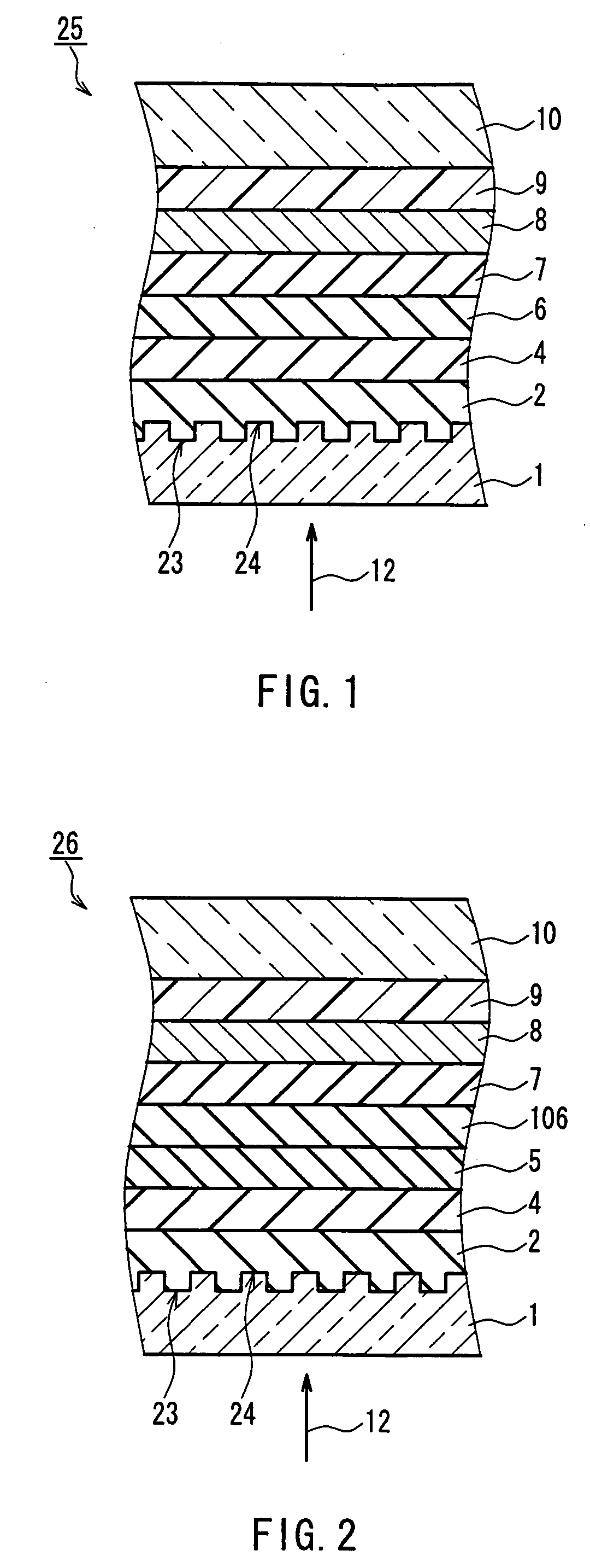
BACKGROUND OF THE INVENTION [0001] 1. Field of the Invention [0002] The present invention relates to an information recording medium on / from which information can be recorded, erased, rewritten and reproduced optically or electrically and a method for producing the same. [0003] 2. Description of the Related Art [0004] An example of the basic structure of an optical information recording medium is such that a first dielectric layer, a recording layer, a second dielectric layer and a reflective layer are formed in this order on a surface of a substrate. The first and the second dielectric layers serve to regulate the optical distance to increase the optical absorption efficiency of the recording layer and increase the difference between the reflectance of the crystalline phase and the reflectance of the amorphous phase to increase the signal amplitude. The dielectric layers also serve to protect the recording layer from moisture or the like. The dielectric layers are formed of, for ex...

Claims


Application Information

Patent Timeline
Patent Type & Authority Applications(United States)
IPC IPC(8): G11B7/243G11B7/253G11B7/24G11B7/2531G11B7/2533G11B7/2534G11B7/257G11B7/2578G11B7/258G11B7/259G11B7/26
CPCG11B7/252Y10S430/146G11B7/2533G11B7/2534G11B7/256G11B7/2578G11B7/259G11B2007/24308G11B2007/24312G11B2007/24314G11B2007/24316G11B2007/25706G11B2007/25708G11B2007/2571G11B2007/25711G11B2007/25713G11B2007/25715H01L45/06H01L45/1233H01L45/144H01L45/1625G11B7/2531H10N70/231H10N70/026H10N70/826H10N70/8828G11B7/2433G11B7/26
Inventor KOJIMA, RIEDOI, YUKAKOYAMADA, NOBORU
Owner PANASONIC CORP
Why Eureka
Eureka Blog
Learn More