This helps you quickly interpret patents by identifying the three key elements:
Problems solved by technology
Method used
Benefits of technology
[0008] The steerable distal support system of the present invention may be used as a support or access system and can be navigated to and positioned at the target site, with or without the use of a separate guidewire. The steerable distal support system of the present invention provides the flexibility, maneuverability, torqueability (usually 1:1), and columnar strength necessary for accurately advancing through the tortuous vasculature either over a standard guidewire or on its own. In embodiments, in which the proximal port assembly is removable, the steerable distal support system itself may be considered to be a hollow guidewire.
[0009] Many thin walled polymeric based catheters do not have sufficient maneuverability or torqueability to be advanced through tortuous body lumens on their own and must be navigated to an occlusion over a standard guidewire. In order for these polymeric catheters to be used as working channels, to physically support devices inserted within the catheter lumen intended to penetrate or otherwise treat such lesions, the wall thickness must be increased, which results in a reduction of the size of the inner axial lumen. In contrast, the steerable distal support systems of the present invention typically has a thin wall construction while still providing sufficient torqueability and maneuverability to be advanced through the body lumen, either over a stan
Problems solved by technology
Many thin walled polymeric based catheters do not have sufficient maneuverability or torqueability to be advan
Method used
Image
Click on the blue label to locate the original text in one second.
Reading with bidirectional positioning of images and text.
Examples
Embodiment Construction
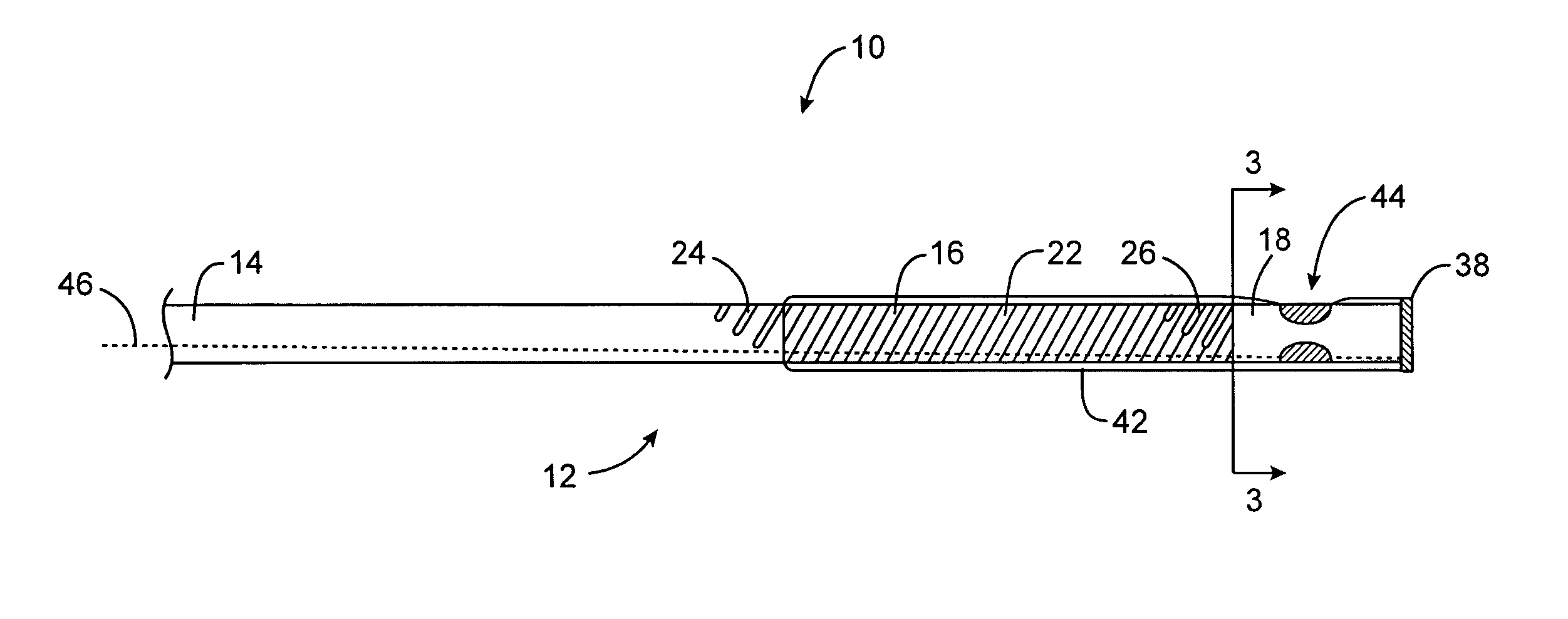
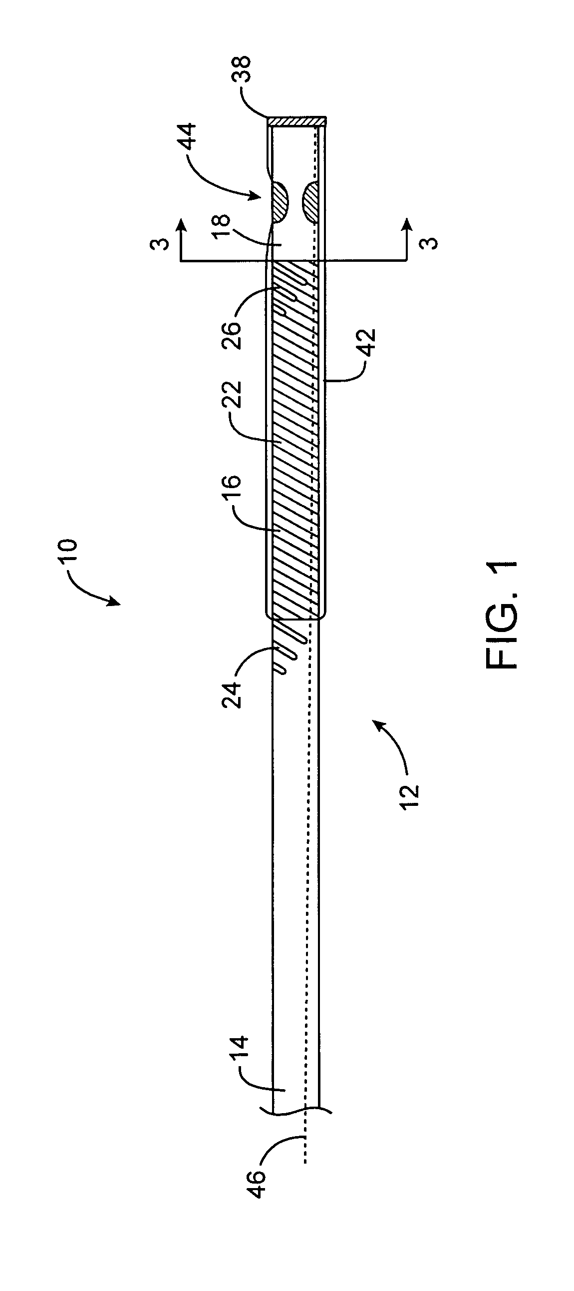
[0039] The present invention provides a steerable distal support system that is in the form of catheter or hollow guidewire so as to define a working channel for an interventional device. The steerable distal support system of the present invention is typically comprised of one or more tubular bodies such as hypotubes. At least some of the hypotubes may be selectively etched to create spiral etchings that have a varying pitch along the length of the steerable distal support system so as to create one or more flexible, soft atraumatic coils. By varying the pitch of the spiral coils, a user may selectively create stiff and flexible portions along the length of the steerable distal support system. As will be described in greater detail below, the steerable distal support system in FIG. 1 comprises three separate coils coupled to each other to form the elongate body of the steerable distal support system. In contrast, the embodiments of FIGS. 11 and 13 are comprised of a single laser et...
PUM
Abstract
A steerable distal support system for accessing stenosis, partial occlusions, or complete occlusions within a body lumen. The steerable distal support system generally includes an elongate member that comprises a proximal portion, a more flexible intermediate portion and a deflectable distal tip. The deflectable distal tip is at a distal end of the elongate body to facilitate directionality and positioning of the steerable distal support system to the target site. Optionally, an expandable centering assembly may be disposed on the steerable support assembly to center and anchor the steerable support assembly within the body lumen.
Description
CROSS-REFERENCES TO RELATED APPLICATIONS [0001] The present invention is a continuation-in-part application of U.S. patent application Ser. No. 09 / 935,534, now U.S. Patent No. U.S. Pat. No. 6,746,422, which claims the benefit of U.S. Provisional Application No. 60 / 228,012, filed Aug. 23, 2000, the complete disclosures of which are incorporated herein by reference. [0002] The present application is also related to U.S. patent application Ser. No. 09 / 030,657, filed Feb. 25, 1998, now U.S. Pat. No. 6,059,767, U.S. Provisional Patent Application No. 60 / 195,154, filed Apr. 6, 2000, and U.S. patent application Ser. No. 09 / 644,201, filed Aug. 22, 2000, the complete disclosures of which are incorporated herein by reference.BACKGROUND OF THE INVENTION [0003] The present invention is generally related to medical devices and methods. More specifically, the present invention provides a steerable distal support system for accessing stenosis, partial occlusions, or total occlusions in a patient's...
Claims
Application Information
Patent Timeline
Application Date:The date an application was filed.
Publication Date:The date a patent or application was officially published.
First Publication Date:The earliest publication date of a patent with the same application number.
Issue Date:Publication date of the patent grant document.
PCT Entry Date:The Entry date of PCT National Phase.
Estimated Expiry Date:The statutory expiry date of a patent right according to the Patent Law, and it is the longest term of protection that the patent right can achieve without the termination of the patent right due to other reasons(Term extension factor has been taken into account ).
Invalid Date:Actual expiry date is based on effective date or publication date of legal transaction data of invalid patent.