Polymeric stent and method of manufacture

a polymer stent and manufacturing method technology, applied in the field of medical devices, can solve the problem of greater force needed to shape, and achieve the effect of maintaining some flexibility and increasing the force needed to shape i

Inactive Publication Date: 2005-01-27
NANYANG TECH UNIV
View PDF50 Cites 106 Cited by
  • Summary
  • Abstract
  • Description
  • Claims
  • Application Information

AI Technical Summary

Benefits of technology

[0010] A polymer that is amorphous, or is at least partially amorphous, will undergo a transition from a pliable, elastic state (at higher temperatures) to a brittle glass-like state (at lower temperatures) as it transitions through a particular temperature, referred to as the glass transition temperature (Tg). The glass transition temperature for a given polymer will vary, depending on the size and flexibility of side-chains, as well as the flexibility of the backbone linkages and the size of functional groups incorporated into the polymer backbone. Below Tg, the polymer will maintain some flexibility, and may be deformed to a new shape. However, the further the temperature below Tg the polymer is when being deformed, the greater the force needed to shape it.

Problems solved by technology

However, the further the temperature below Tg the polymer is when being deformed, the greater the force needed to shape it.

Method used


Image

  • Polymeric stent and method of manufacture
  • Polymeric stent and method of manufacture
  • Polymeric stent and method of manufacture

Examples


example 1

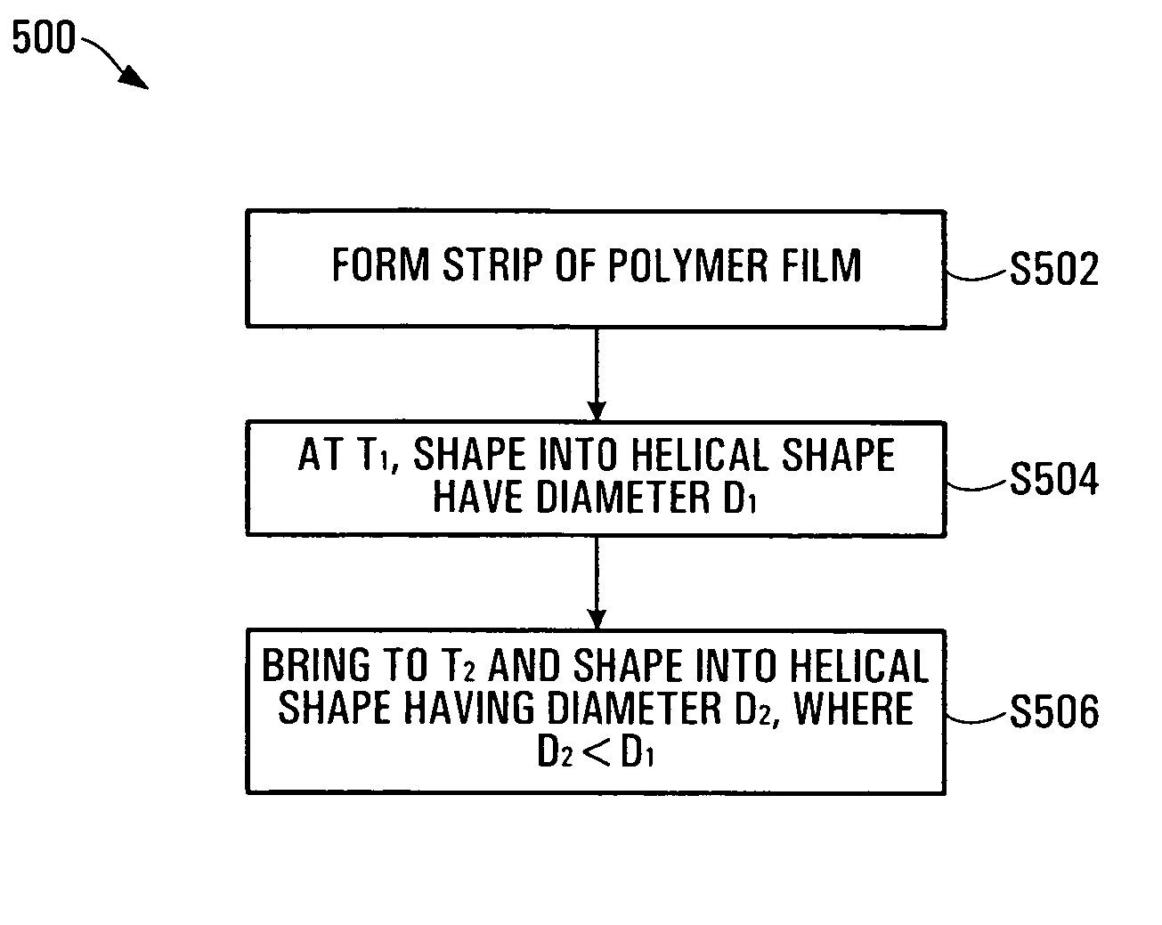
Manufacture of the Stent

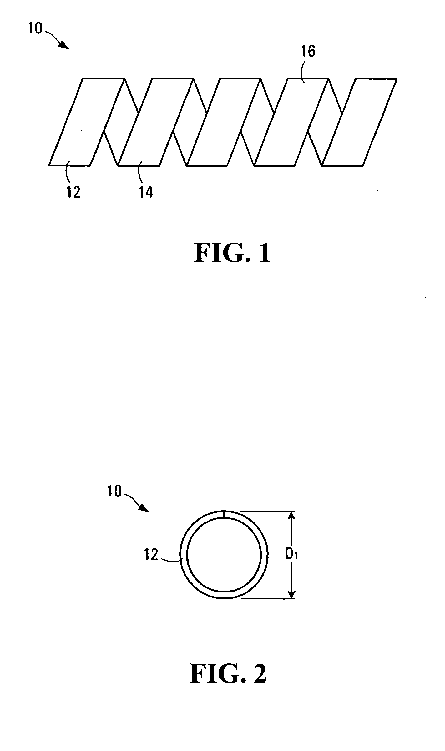
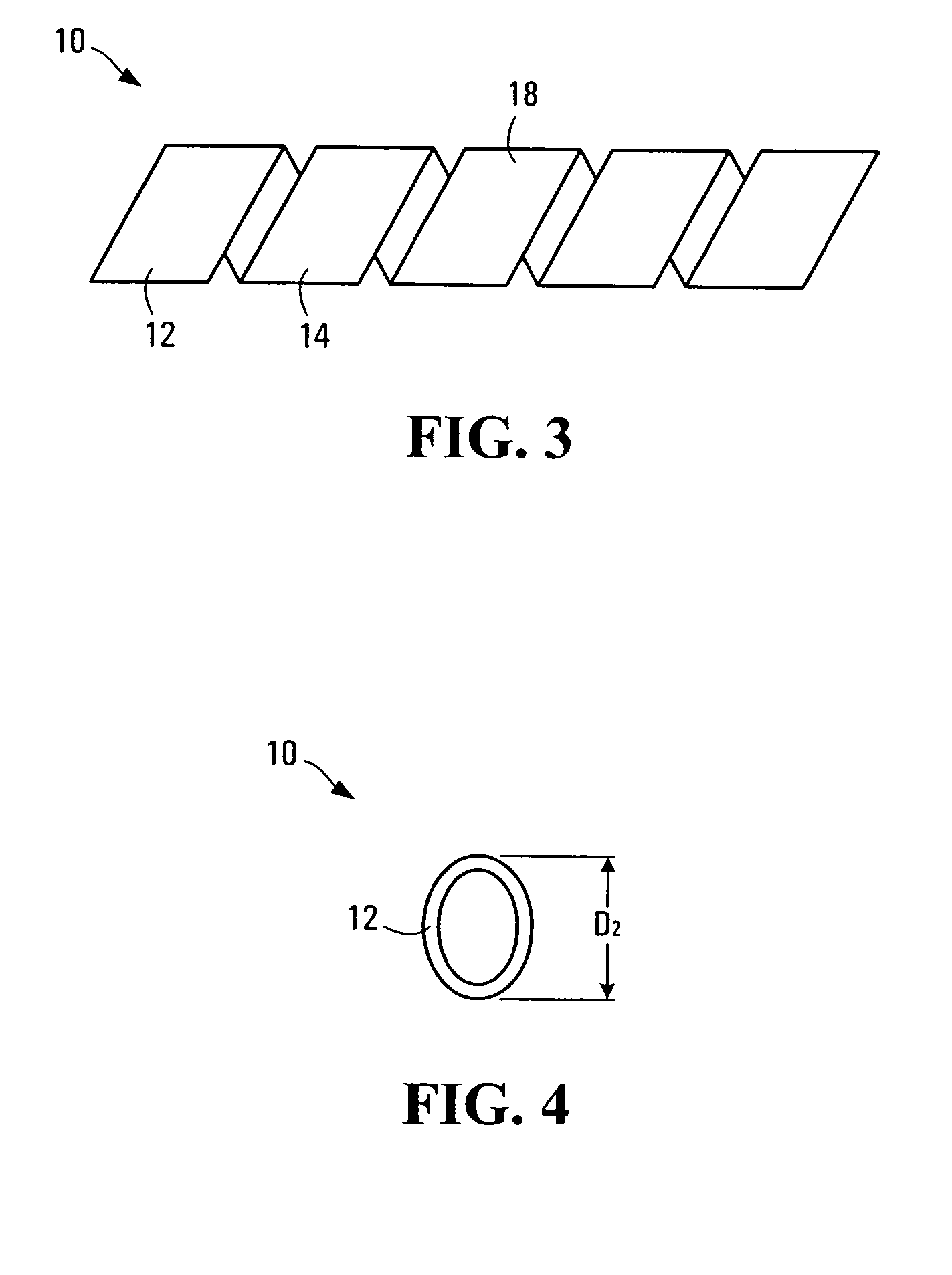
[0110] A strip of polymer film is made by the usual methods (solvent-casting or extrusion). Next, the strip is coiled into a helical shape and set into this shape (helical width is D1) at a higher temperature (T1). The choice of T1 depends on the Tg of the polymer: the general rule is to select T1 such that T1 is from Tg to about Tg+40° C. Once set at the higher temperature (T1), the stent is usually made into a helix of smaller helical width (D2); the ratio of D1 / D2 is generally greater than 1, such as from 6 to 2) at a lower temperature (T2): again, T2 may range from T1 less from about 5 to 80° C.

[0111] At this lower helical width, the stent may be deployed easily using a conventional catheter. Once inside the body vessel or cavity, the stent may be expanded by using both pressure and a raised temperature (this temperature is usually between T1 and T2 and is referred to as T3, i.e. T1>T3>T2). Under these conditions, the stent expands quickly first due to ...

example 2

Generation of Multi-Layered Stent

[0114] The preferred configuration of the stent is a multi-layered helical stent, in which the outer layer(s) are made of an amorphous polymer with a Tg between 40° C. and 60° C., while the inner layer is made of an amorphous or semi-crystalline polymer with a higher Tg (60-100° C.), and crystalline melting point greater than 100° C. This ensures rapid expandability.

[0115] To make a two-layered stent, the following procedure is adopted.

[0116] The inner layer (made from PLA, for example) is made by casting the polymer (with or without drug) from a solution in dichloromethane. A standard solution coater is used for this purpose. Next, a solution of the outer-layer polymer (typically a PLGA) is made in a solvent that does not dissolve the inner polymer that is already cast. An example of such a solvent is acetone. This solution is then cast onto the inner layer polymer, and dried to make the two-layer stent film. The film is then shaped into a helica...

example 3

Stent Expansion

[0120]FIG. 12 is a graphical representation showing expansion rate data of for single-layer and double-layer stents at 37° C.


PUM

PropertyMeasurementUnit
widthaaaaaaaaaa
temperatureaaaaaaaaaa
oven temperatureaaaaaaaaaa

Abstract

A stent formed of polymeric material, useful for the expansion of a lumen and the delivery of one or more therapeutic agents in situ is disclosed. The stent may be multi-layered, and may change shape at a state transition temperature governed by the materials forming the layers. Methods of use and manufacture are also disclosed.

Description

CROSS-REFERENCE TO RELATED APPLICATIONS [0001] The present application claims priority from U.S. provisional patent application No. 60 / 478,887, filed Jun. 16, 2003, the contents of which are hereby incorporated by reference herein.FIELD OF THE INVENTION [0002] The present invention relates generally to medical devices for implanting in a patient, and particularly to stents that may be self expanding, and may deliver therapeutic agents. BACKGROUND OF THE INVENTION [0003] Expandable medical prostheses, frequently referred to as stents, are well known and commercially available. They are, for example, disclosed generally in U.S. Pat. No. 4,655,771 (Wallsten), U.S. Pat. No. 5,061,275 (Wallsten et al.) and U.S. Pat. No. 5,645,559 (Hachtmann et al.). Stents are used within body vessels of humans for a variety of medical applications. Examples include intravascular stents for treating stenoses, stents for maintaining openings in the urinary, biliary, tracheobronchial, oesophageal and renal...

Claims


Application Information

Patent Timeline
Patent Type & Authority Applications(United States)
IPC IPC(8): A61F2/82A61F2/88B29C47/06
CPCA61F2/82A61F2/88Y10T156/10A61L31/14A61F2210/0076A61L31/04A61L27/34A61L27/54
Inventor VENKATRAMAN, SUBRAMANIANBOEY, YIN CHIANG
Owner NANYANG TECH UNIV
Why Eureka
Try Eureka