Seal and sealing process for electroluminescent displays

a technology of electroluminescent displays and sealing processes, applied in the direction of discharge tubes/lamp details, discharge tubes luminescnet screens, electric discharge lamps, etc., can solve the problems of shortening the life of displays, reducing the luminosity of displays to usable levels, and reducing the efficiency of display operation, so as to improve the operating stability of displays and reduce the flux of atmospheric contaminants. , the effect of increasing the operating devi

Inactive Publication Date: 2005-02-03
IFIRE IP CORP
View PDF25 Cites 34 Cited by
  • Summary
  • Abstract
  • Description
  • Claims
  • Application Information

AI Technical Summary

Benefits of technology

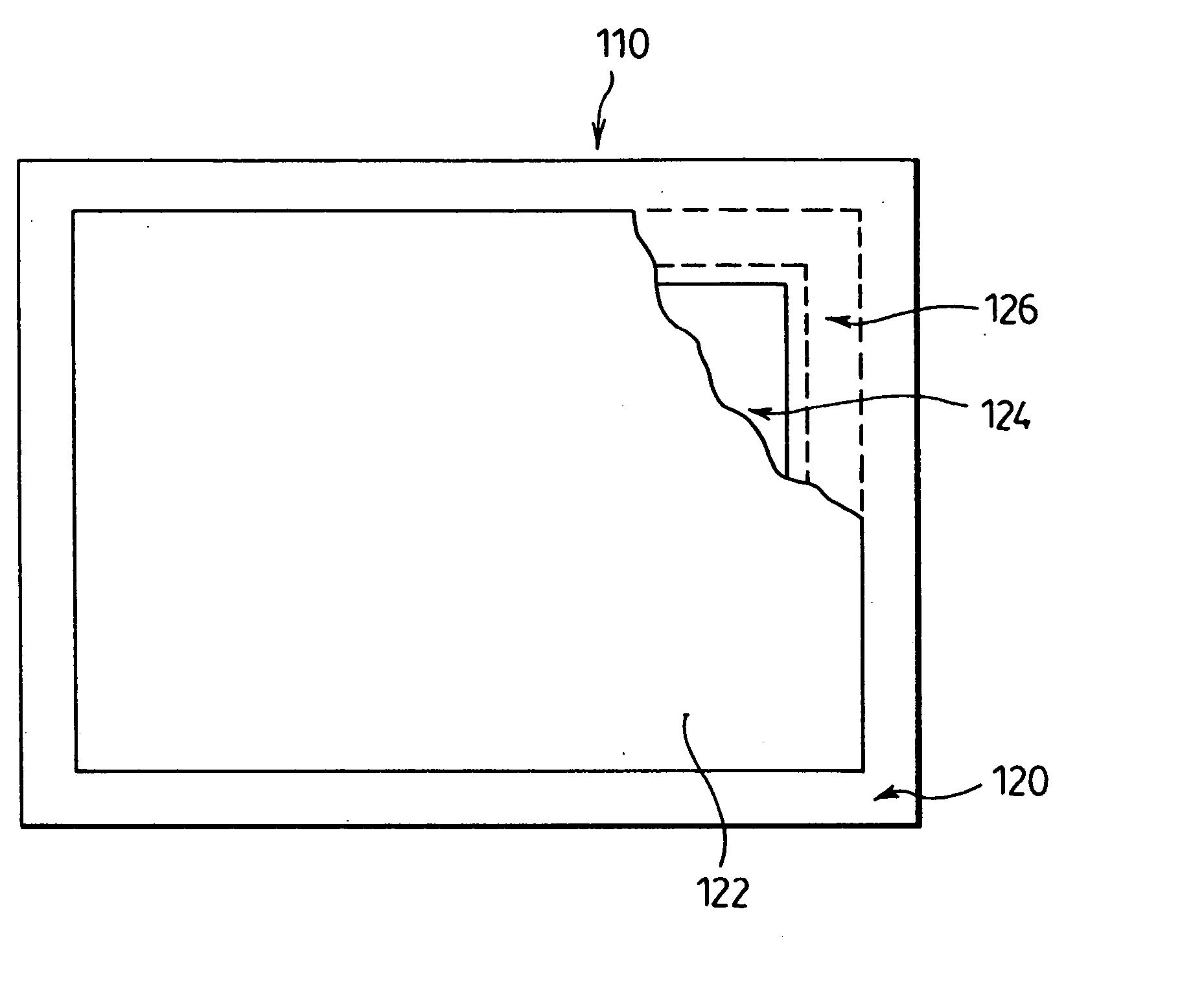
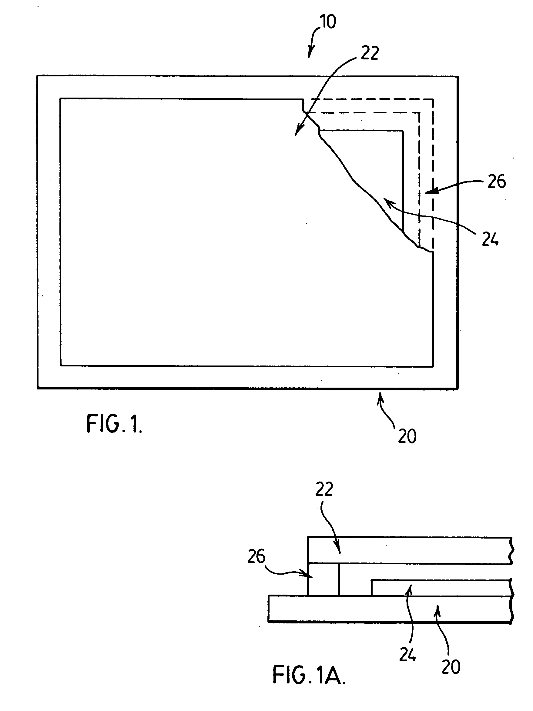
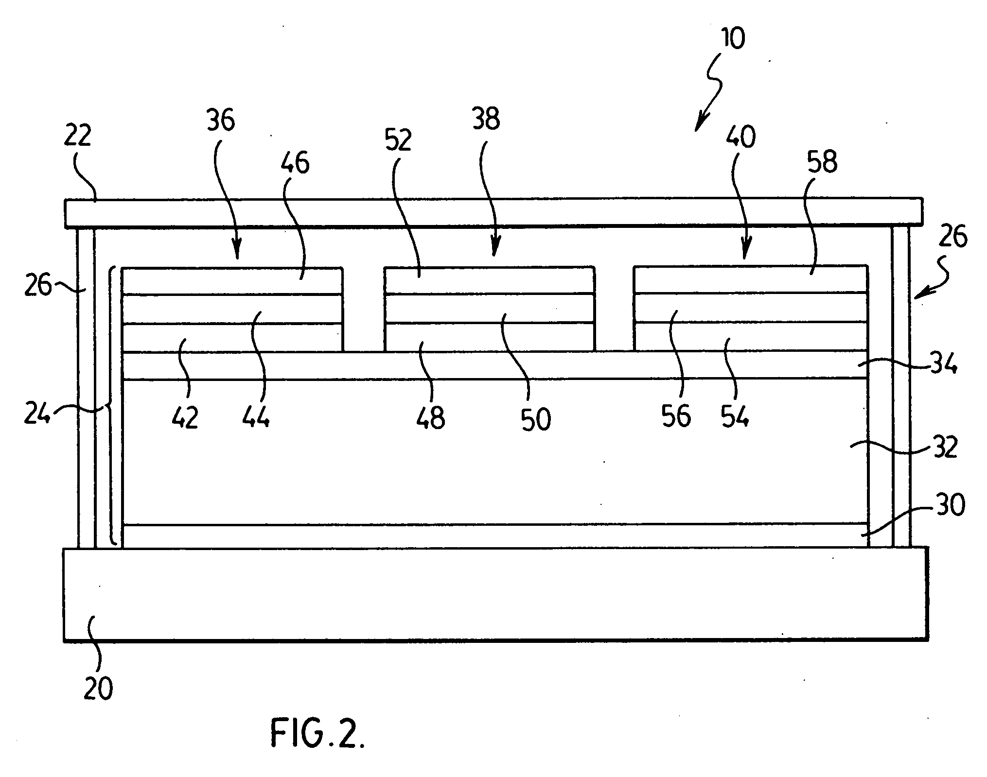
[0012] The invention is directed to a seal and sealing process for electroluminescent displays to improve operating stability of the displays. The seal is a perimeter seal which contacts and extends from the substrate of the display to the cover plate of the display to effectively minimize the flux of atmospheric contaminants that may negatively affect the electroluminescent display structure that is provided in between the cover plate and the substrate. In other words, the perimeter seal occupies the entire height of the gap between the substrate and the cover plate. The perimeter seal does not impede the functioning of the electroluminescent display structure. The provision of the perimeter seal helps to increase the operational device of the electroluminescent display in which it is incorporated.
[0020] a perimeter seal contacting and extending from the substrate and to the cover plate to inhibit exposure of the electroluminescent display structure to an atmospheric contaminant.

Problems solved by technology

Exposing conventional electroluminescent displays to atmospheric contaminants is known to shorten the life of displays.
Thick film dielectric electroluminescent displays typically employ phosphor materials and insulator materials that are susceptible to degradation due to reaction with atmospheric vapours.
Further, the thick dielectric layer of such displays, which enhances the luminosity of the displays to usable levels, may also be susceptible to degradation due to reaction with atmospheric contaminants.
This type of barrier tends to have limited utility due to the large area to thickness ratio which results in a relatively high rate of transport of vapour species therethrough.

Method used


Image

  • Seal and sealing process for electroluminescent displays
  • Seal and sealing process for electroluminescent displays
  • Seal and sealing process for electroluminescent displays

Examples


example 1

[0080] This example illustrates the ability of getter material, which is mixed into a sealing material, to absorb moisture from normal ambient air. 30Y-296C UV curable adhesive obtained from Three Bond International Inc. of West Chester Ohio, USA was mixed with 20% by weight of 3× molecular sieve powder having an average particle size of about 5 micrometers. Before mixing, the molecular sieve powder was first activated at 300° C. for one hour.

[0081] The mixed getter material and sealing material was subsequently spread on a plate to a thickness of 0.3 to 0.5 millimeters and UV cured to form a film. The film on the plate was then placed in air which contained 1500 parts per million water. The film was maintained at a temperature of about 23° C. and the weight gain of the film was monitored over time. FIG. 5 shows the weight gain of the film as a function of time. The weight of the film increased linearly over time by about 2.5% over 800 hours. For comparison, a similar film without ...

example 2

[0082] This example is similar to Example 1, except that the sealing material consisted only of UVS91 UV curable adhesive from Norland Products Inc. of Cranbury, N.J., USA rather than 30Y-296C UV curable adhesive. The results are shown in FIG. 6. FIG. 6 shows that the weight of the film containing molecular sieves increased relatively quickly over about 200 hours by about 2.5% and then became constant at about 3%. As for Example 1, there was no appreciable weight gain when the sealing material did not contain molecular sieves. This example shows that the permeation rate for water in the UVS91 UV curable adhesive is significantly faster than it is for the blended adhesive of Example 1.

example 3

[0083] This example shows the ability of a getter material, dispersed in a sealing material, to reduce the partial pressure of water vapour in a sealed volume. A 0.225 gram sample of 13× molecular sieve dispersed in UVS91 UV curable adhesive, similar to that of Example 2, was enclosed in a 130 cm3 sealed cell fitted with a dew point probe. FIG. 7 shows the measured water vapour concentration in the cell as a function of time. The moisture content in the cell was reduced to about 100 ppm in about 100 hours, which shows the efficacy of the material to absorb water at low vapour concentrations.


PUM


Abstract

The present invention is a sealed electroluminescent display that incorporates a perimeter seal that inhibits exposure of display components to atmospheric contaminants and to a sealing process for fabrication of the same. The sealed electroluminescent display comprises a substrate, a cover plate and an electroluminescent display structure between the substrate and the cover plate. A perimeter seal is provided that extends from the substrate to the cover plate to inhibit exposure of the electroluminescent display structure to an atmospheric contaminant. The perimeter seal comprises one or more layers of a sealing material wherein at least one of the layers further comprises a getter material.

Description

FIELD OF THE INVENTION [0001] The present invention relates to electroluminescent displays. In particular, the present invention relates to an electroluminescent display having a perimeter seal that inhibits exposure of display components to at least one atmospheric contaminant and to a sealing process for fabrication of the same. BACKGROUND TO THE INVENTION [0002] Exposing conventional electroluminescent displays to atmospheric contaminants is known to shorten the life of displays. To protect electroluminescent displays, various types of seals have been utilized. [0003] In electroluminescent displays employing thin film phosphors, phosphor materials are typically sandwiched between a pair of addressable electrodes, and usually fabricated on a glass, a glass ceramic, ceramic, or other heat resistant substrate. The phosphor materials are activated by application of an electric field generated between the electrodes. These displays can be protected from atmospheric contaminants by pla...

Claims


Application Information

Patent Timeline
Patent Type & Authority Applications(United States)
IPC IPC(8): H01J1/62H01L51/52H05B33/04
CPCH05B33/04H01L51/5237H10K50/8426H10K50/846H05B33/10
Inventor WANG, YUXIN
Owner IFIRE IP CORP
Why Eureka
Try Eureka