Power distribution system with a dedicated power structure and a high performance voltage regulator

a power distribution system and voltage regulator technology, applied in the direction of electrical apparatus construction details, cross-talk/noise/interference reduction, liquid/fluent solid measurement, etc., can solve the problems of reducing the design of the pcb, consuming a significant portion of the pcb resources, and reducing the efficiency of the pcb, so as to save space and reduce the inductance , the effect of saving space on the pcb

Inactive Publication Date: 2005-02-03
SUN MICROSYSTEMS INC
View PDF28 Cites 9 Cited by
  • Summary
  • Abstract
  • Description
  • Claims
  • Application Information

AI Technical Summary

Benefits of technology

[0015] The power laminate may also include a plurality of decoupling capacitors. In one embodiment, the decoupling capacitors may be surface-mounted capacitors. Mounting the decoupling capacitors on the power laminate may save a significant amount of space on the PCB.
[0016] Thus, in various embodiments, the system for distributing power to an integrated circuit including a power laminate may provide various advantages. By distributing power to the integrated circuit using a power laminate, a PCB may be optimized for signal distribution and routing, while the power laminate is optimized for core power distribution. Compromises to both core power distribution and signal distribution that occur when both are implemented on the PCB may be avoided. Placing all core power distribution functions on the power laminate, including a voltage regulator circuit and decoupling capacitors may result in a significant savings of space on the PCB. Furthermore, distribution of core power by a power laminate may result in a power connection with lower inductance than can be achieved by distributing power on the PCB. This low-inductance power connection may result in a significant lowering of impedance in the power distribution system. With a low impedance power connection, power may flow more easily from the power distribution system to the integrated circuit.

Problems solved by technology

These demands make design of a power distribution system increasingly difficult.
Power distribution to a processor or ASIC can consume a significant portion of PCB resources, and is but one of several competing demands which must be considered during the PCB's design.
These demands are often times in conflict with one another, and thus compromises must be made to the design of the PCB.
Such compromises may result in a less than optimal solution in addressing some or all of these demands.
The presence of these signal vias may have a tendency to increase the inductance of the copper planes, which in turn results in an increase in impedance.
Further compounding problems of power distribution on a PCB is the fact that many computer systems required different voltages for various components.
This may further increase the number of vias necessary in the PCB, thereby increasing the inductance of each of the power planes.

Method used


Image

  • Power distribution system with a dedicated power structure and a high performance voltage regulator
  • Power distribution system with a dedicated power structure and a high performance voltage regulator
  • Power distribution system with a dedicated power structure and a high performance voltage regulator

Examples


Embodiment Construction

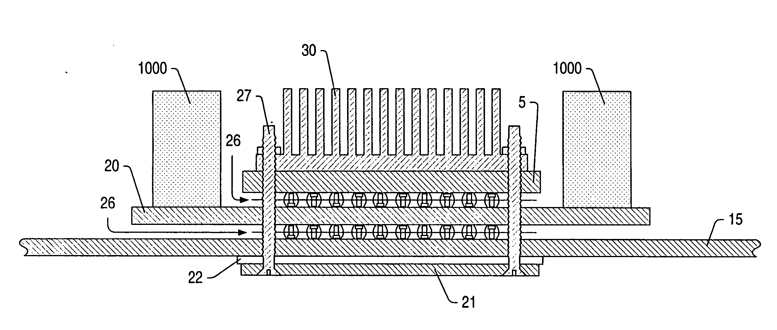
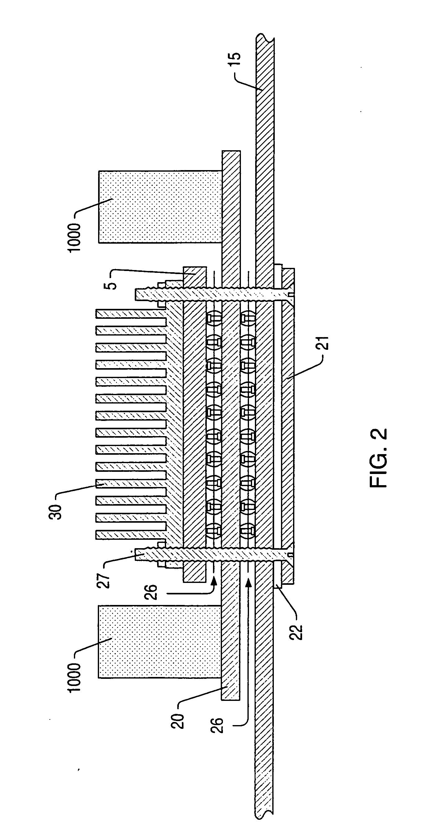
[0026] Turning now to FIG. 1, a drawing illustrating one embodiment of a power distribution system, including a power laminate, for an integrated circuit is shown. Integrated circuit 5 is mounted to printed circuit board (PCB) 15 by solder balls 25, which are part of a ball-grid array (BGA). Heat sink 30 may be mounted upon integrated circuit 5 for the purposes of dissipating heat.

[0027] Power laminate 20 may be mounted to PCB 15 on the opposite side of integrated circuit 5, also by a BGA. Power laminate 20 may be configured for the distribution of all power to integrated circuit 5. Power laminate 20 may include at least one power plane and one reference (e.g. ground) plane. In the embodiment shown, PCB 15 does not include power or ground planes for providing power to the integrated circuit, and thus is not configured for providing power to the integrated circuit. This may allow PCB 15 to be optimized for signal distribution, while power laminate 20 is optimized for power distribut...


PUM

PropertyMeasurementUnit
currentaaaaaaaaaa
voltageaaaaaaaaaa
voltageaaaaaaaaaa

Abstract

A system and method for distributing power to an integrated circuit. In one embodiment, a power laminate may be mounted to a printed circuit board (PCB). The integrated circuit for which power is to be distributed may be electrically coupled to the PCB. The power laminate may include one or more power planes and one or more reference (i.e. ground) planes, with each pair of power/reference planes separated by a dielectric layer. The power laminate may also include a connector or other means for receiving power from an external power source. The power laminate may be electrically coupled to the integrated circuit, thereby enabling it to provide power to the integrated circuit. The power laminate may also include a voltage regulator circuit, and a plurality of decoupling capacitors.

Description

PRIORITY DATA [0001] This application claims priority to U.S. provisional application Ser. No. 60 / 244,399, entitled “Power Distribution System with a Dedicated Power Structure and a High Performance Voltage Regulator” filed Oct. 30, 2000.BACKGROUND OF THE INVENTION [0002] 1. Field of the Invention [0003] This invention relates to electronic circuits, and more particularly, to the distribution of power to electronic circuits. [0004] 2. Description of the Relevant Art [0005] With each new generation of computer systems, performance demands increase. One such demand relates to power distribution systems, which are required to supply increasing currents at lower voltages and lower impedances. These demands make design of a power distribution system increasingly difficult. [0006] In many computer systems, processors and application specific integrated circuits (ASICs) are the chief consumers of power. Power is typically delivered to these components through a printed circuit board (PCB)....

Claims


Application Information

Patent Timeline
Patent Type & Authority Applications(United States)
IPC IPC(8): G06F1/26H05K1/02H05K1/14H05K3/32H05K3/34H05K3/36
CPCG06F1/26H05K1/0231H05K1/0262H05K1/141H05K3/325H05K3/3436Y10T29/4913H05K2201/09309H05K2201/10545H05K2201/10734Y10T29/49144Y10T29/49117H05K3/368
Inventor SMITH, LARRY D.NOVAK, ISTVANFREDA, MICHAEL C.
Owner SUN MICROSYSTEMS INC
Why Eureka
Try Eureka