Grating forming method, molding die, molded product and manufacturing method for master member for manufacturing molding die

a technology of molding die and molding die, which is applied in the direction of instruments, coatings, optics, etc., can solve the problems of long working time, inability to perform mass production, and inability to deburr, so as to reduce the roughness and swelling of the surface, reduce the manufacturing cost, and restrict the forming of the burr

Inactive Publication Date: 2005-02-03
SANKYO SEIKI MFG CO LTD
View PDF3 Cites 27 Cited by
  • Summary
  • Abstract
  • Description
  • Claims
  • Application Information

AI Technical Summary

Benefits of technology

In view of the problems described above, it is an object and advantage of the present invention to provide a grating forming method by which the forming of a burr is restricted when a fine grating with a grating period of 1 μm or less is formed by a mechanical process and capable of reducing the roughness and the swelling of the surface of the fine grating. Further, it is another object and advantage of the present invention to provide a molding die on which a fine grating is formed on its forming surface by the grating forming method, a molded product where the shape of the fine grating formed on the molding die is transferred on its surface, and a manufacturing method for a master member for manufacturing a molding die on which a fine grating is formed on its forming surface.
to provide a grating forming method by which the forming of a burr is restricted when a fine grating with a grating period of 1 μm or less is formed by a mechanical process and capable of reducing the roughness and the swelling of the surface of the fine grating. Further, it is another object and advantage of the present invention to provide a molding die on which a fine grating is formed on its forming surface by the grating forming method, a molded product where the shape of the fine grating formed on the molding die is transferred on its surface, and a manufacturing method for a master member for manufacturing a molding die on which a fine grating is formed on its forming surface.
Further, it is another object and advantage of the present invention to provide an anti-reflection member capable of reducing the manufacturing cost by applying the above-mentioned grating forming method to the forming of minute projections constructing a grating. Further, it is another object and advantage of the present invention to provide a molding die for an anti-reflection member and a manufacturing method for a master member for manufacturing a molding die for an anti-reflection member.
In order to achieve the above object and advantage, according to an embodiment of the present invention, there is provided a grating forming method for forming a fine grating with a grating period of 1 μm or less on a surface of a blank material including cutting the surface of the blank material with a blade tip part of a diamond cutting tool. In the embodiment of the present invention, in the case that the fine grating with the grating period of “P”μm is formed and the feed speed of the diamond cutting tool is set to be “F” mm / min, the feed speed “F” is set so as to satisfy the following conditional expression (1):
Also, in order to achieve the above object and advantage, according to another embodiment of the present invention, there is provided a grating forming method for forming a fine grating with a grating period of 1 μm or less on a surface of a blank material including cutting the surface of the blank material with a blade tip part of a diamond cutting tool. In the embodiment of the present invention, in the case that the fine grating with the grating period of “P”μm is formed and the vibration amplitude of the diamond cutting tool (in a perpendicular direction with respect to the surface of the blank material) is set to be “A”μm, the vibration amplitude “A” is set so as to satisfy the following conditional expression (2):
Also, in order to achieve the above object and advantage, according to a further embodiment of the present invention, there is provided a grating forming method for forming a fine grating with a grating period of 1 μm or less on a surface of a blank material including cutting the surface of the blank material with a blade tip part of a diamond cutting tool. In the embodiment of the present invention, in the case that the fine grating with the grating period of “P”μm is formed and the feed amount per revolution of the diamond cutting tool is set to be “S”μm, the feed amount per revolution “S” is set so as to satisfy the following conditional expression (3):

Problems solved by technology

However, in order to perform the thin film technique, expensive facilities such as a film forming equipment, an exposure equipment, a lithography equipment, and an etching equipment are required.
In addition, since a long time is required for processing, mass production can not be performed.
On the contrary, a long working time is required when a deburring is performed after cutting work.
However, when the multi-layer film is used for anti-reflection, the material having an optimal refractive index as the multi-layer film is limited.
Thus a combination of optimal materials may not exist depending on a blank material and the wavelength of the incident light.
Furthermore, the heat resisting properties and the durability may be reduced due to the physical, chemical and thermal inconsistency based on the differences of the materials of the respective layers.
In addition, since the multi-layer film is formed by means of the vapor deposition, the cost of material increases.
However, when the grating comprising many minute projections as described above is formed by mechanical processing, it is very difficult to easily manufacture a grating such that a burr is not formed.

Method used


Image

  • Grating forming method, molding die, molded product and manufacturing method for master member for manufacturing molding die
  • Grating forming method, molding die, molded product and manufacturing method for master member for manufacturing molding die
  • Grating forming method, molding die, molded product and manufacturing method for master member for manufacturing molding die

Examples


application examples

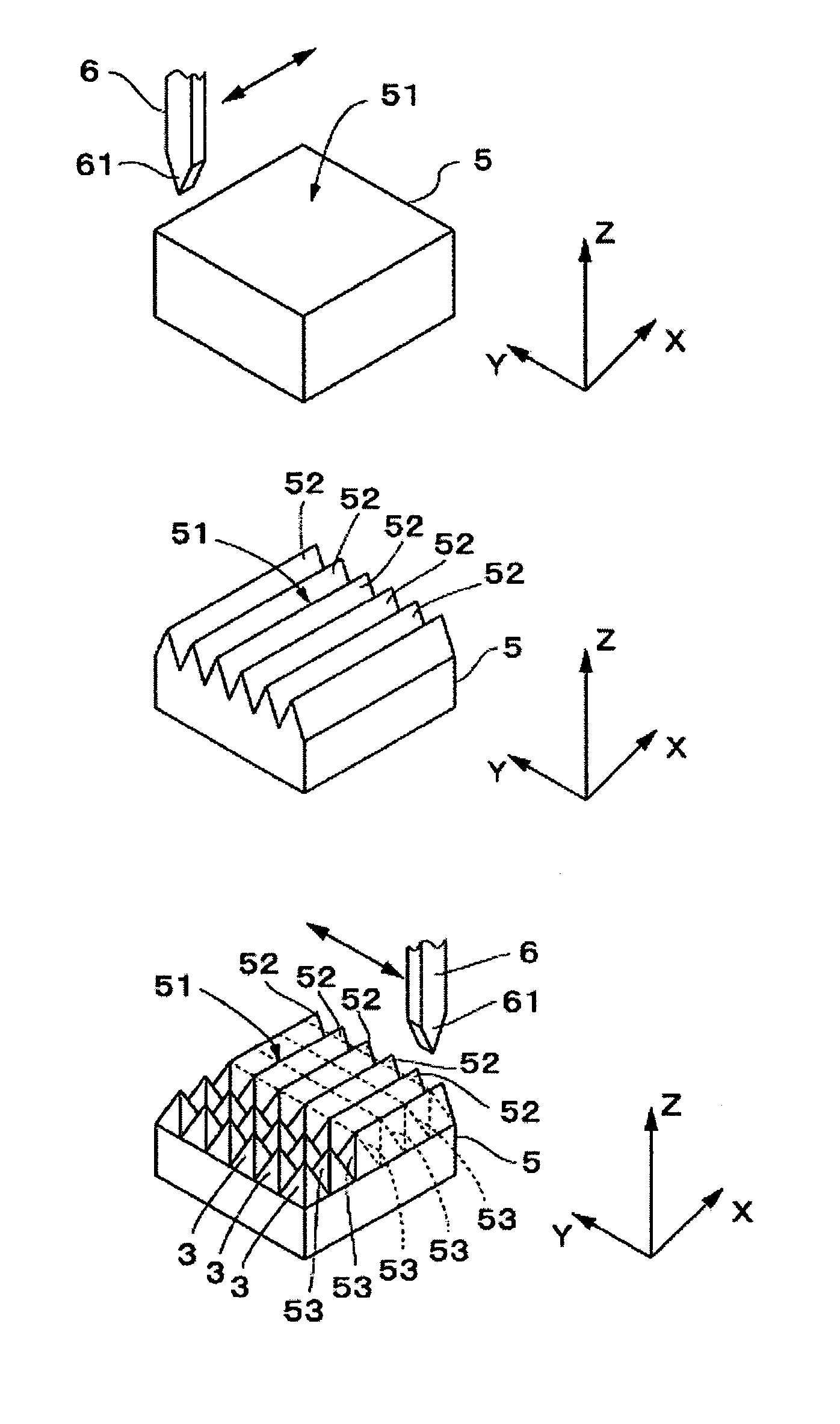
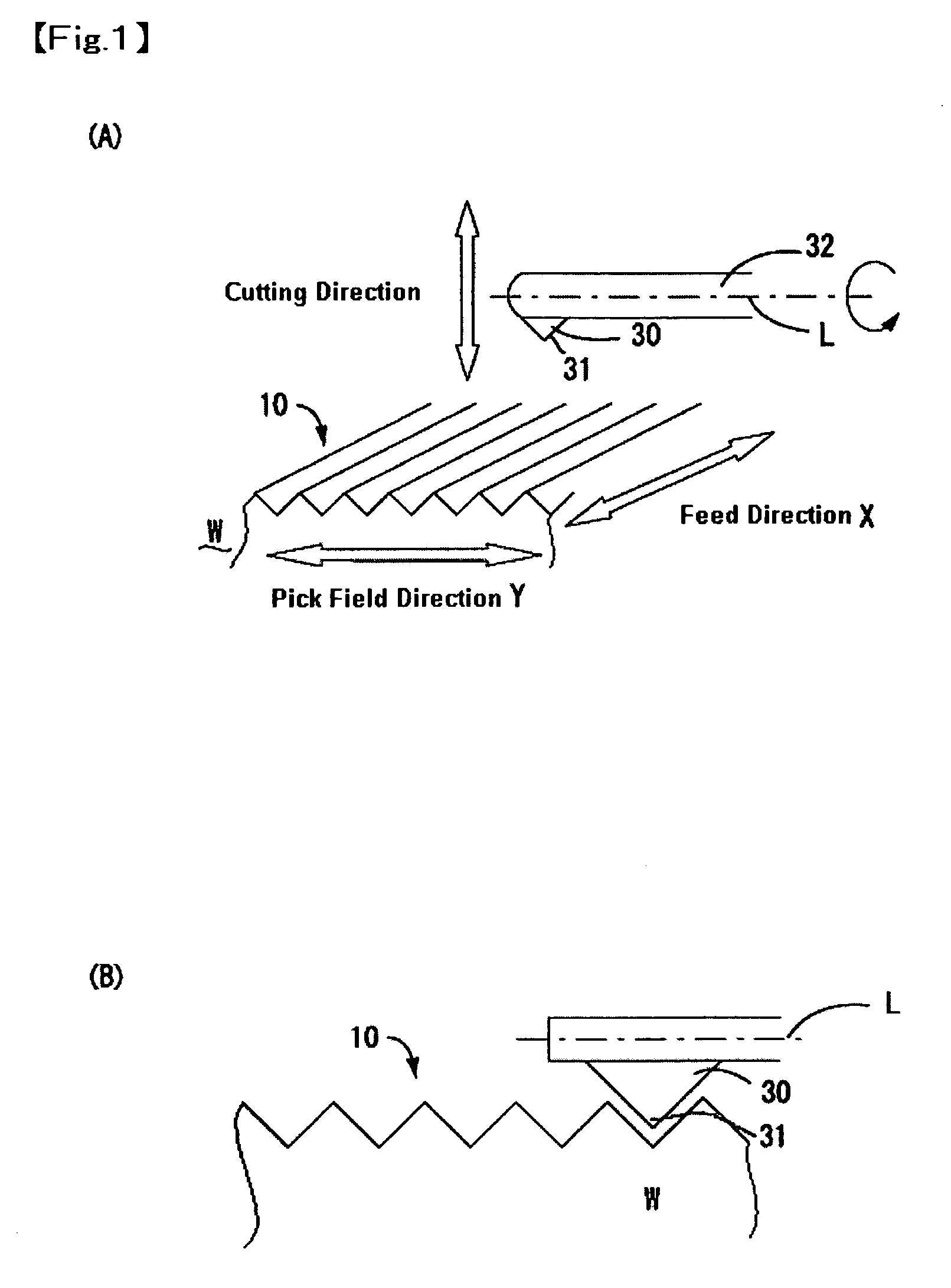
Next, an optical element (anti-reflection member) on which a grating for anti-reflection is formed will be described below, to which the present invention is applied, and a minute projection forming method for forming a pyramid-shaped minute projections for constructing the grating will be described below, to which the present invention is applied.

Construction of Optical Element

FIG. 8(A) is a perspective view showing an optical element on which a grating forming method in accordance with the embodiment of the present invention is applied and FIG. 8(B) is an explanatory view showing a refractive index distribution on the surface of the optical element shown in FIG. 8(A).

An optical element 1 shown in FIG. 8(A) is, for example, a diffraction grating or an objective lens included in a common optical system, which is used in an optical apparatus such as an optical pickup device for performing reproduction or the like from different types of optical record disks such as a CD or a DV...


PUM

PropertyMeasurementUnit
grating periodaaaaaaaaaa
roughnessaaaaaaaaaa
angleaaaaaaaaaa

Abstract

A grating forming method for forming a fine grating with a grating period of 1 μm or less on a surface of a blank material including cutting the surface of the blank material with a blade tip part of a diamond cutting tool. When the fine grating with the grating period of “P”μm is formed and the feed speed of the diamond cutting tool is set to be “F” mm / min, the feed speed “F” is set to satisfy the conditional expression: F<1 0 0 P3. The vibration amplitude of the diamond cutting tool in a perpendicular direction to the surface of the blank material is set to be “A”μm, the vibration amplitude “A” is set to satisfy the following conditional expression: A<0. 0 1 8 P2. The feed amount per revolution of the diamond cutting tool is set to be “S”μm, the feed amount per revolution “S” is set to satisfy the following conditional expression: S<2. 9 P3. These conditional expressions are applied to a blank material, a molding die, a molded product, and a master member for manufacturing a molding die.

Description

CROSS-REFERENCE TO RELATED APPLICATIONS This application claims priority to Japanese Application No. 2003-187886 filed Jun. 30, 2003, Japanese Application No. 2003-332384 filed Sep. 24, 2003, and Japanese Application No. 2003-374051 filed Nov. 4, 2003, which are incorporated herein by reference. FIELD OF THE INVENTION The present invention relates to a grating forming method for forming a fine grating with the grating period of 1 μm or less on the surface of a blank material, a molding die where the fine grating is formed on its molding surface by the grating forming method, a molded product where the shape of the fine grating of the molding die is transferred on the surface thereof, and a manufacturing method for a master member for manufacturing a molding die. BACKGROUND OF THE INVENTION A photonic crystal which is an optical material having a refractive index distribution in almost the same period as the wavelength of light beam has gotten a lot of attention as a new optical m...

Claims


Application Information

Patent Timeline
Patent Type & Authority Applications(United States)
IPC IPC(8): G02B1/11G02B5/18
CPCG02B1/11Y10T29/49995G02B5/1852
Inventor HANAOKA, MASASHIHAYASHI, KENICHIYAMAMOTO, MINORU
Owner SANKYO SEIKI MFG CO LTD
Why Eureka
Try Eureka