Polymer electrolyte fuel cell

Inactive Publication Date: 2005-02-03
PANASONIC CORP
View PDF5 Cites 4 Cited by
  • Summary
  • Abstract
  • Description
  • Claims
  • Application Information

AI Technical Summary

Benefits of technology

[0017] Accordingly, it is an object of the present invention to provide a polymer electrolyte fuel cell having an excellent sealing property and a stable output character

Problems solved by technology

However, such a gasket has a problem of being inappropriate for reliably securing a sealing property since a large number of unit cells are stacked to be cramped in a stack.
Therefore, sealing needs to be conducted in two locations: between an anode (fuel electrode) and the electrolyte membrane; and between a cathode (oxidant electrode) and the electrolyte membrane, and that is to say, both a gasket for sealing a fuel gas and a gasket for sealing an oxidant gas are required, raising a problem of enlarging portions needed to be sealed.
This has brought about an increase in stack volume, an increase in cost, and complication of the form of the separator plate, causing a decreased yield in processing the separator plate.
When this clearance is small, it tends to be difficult to reliably build a stack.
For example, the O-ring-shaped gasket may be partially placed or stacked on the electrode to cause poor sealing.
Further, with the O-ring-shaped gasket brought into contact with the electrode, excessive surface pressure is applied onto the electrode, which may result in damage of the electrolyte membrane or deterioration in durability, whereby cell performance may be degraded.
In the case where the clearance between the O-ring-shaped gasket and the electrode is made smaller, therefore, a yield may decrease and cost for components may increase unless dimensional accuracy o

Method used


Image

  • Polymer electrolyte fuel cell
  • Polymer electrolyte fuel cell
  • Polymer electrolyte fuel cell

Examples


Example

EXAMPLE 1

[0109] (i) Production of Separator Plate

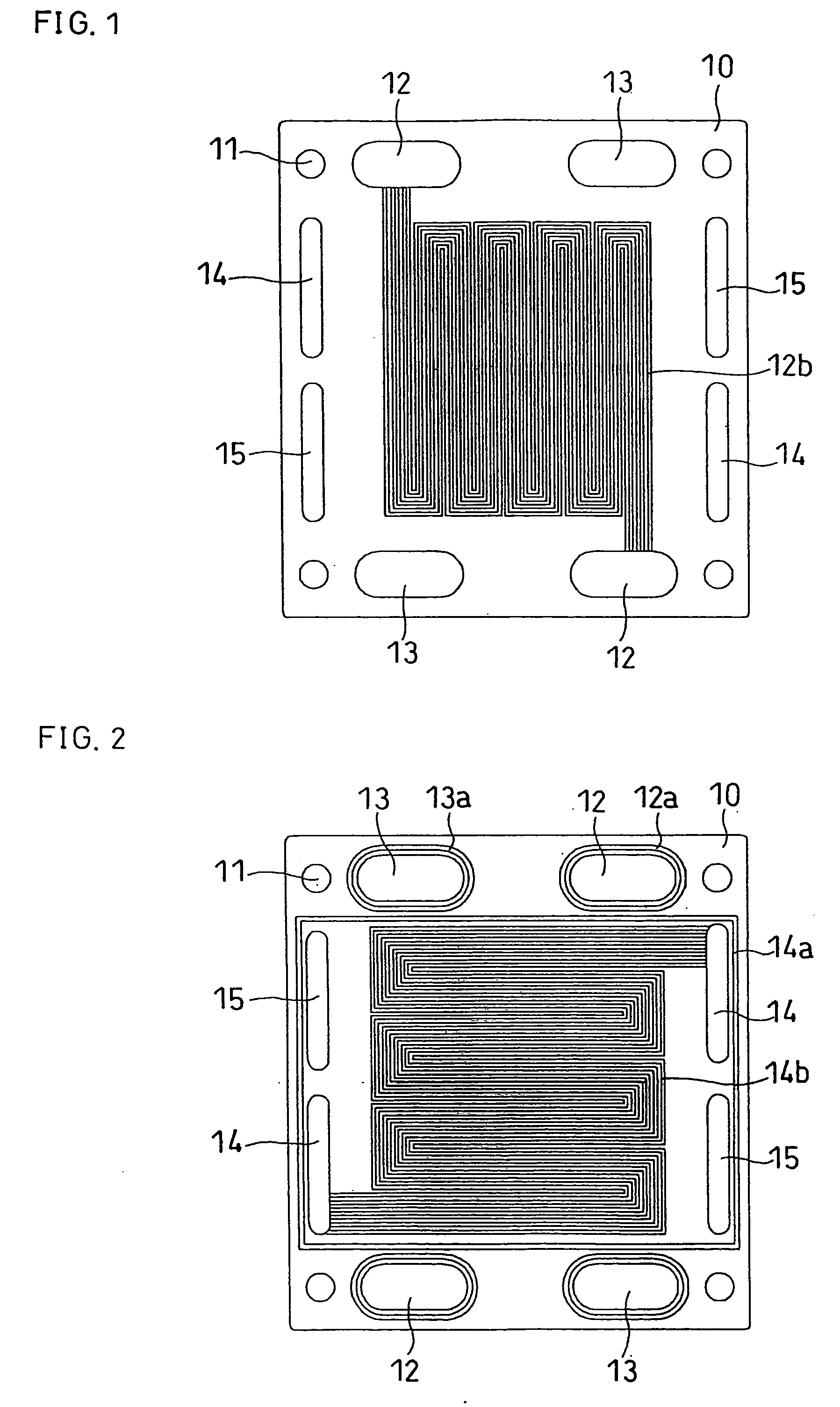
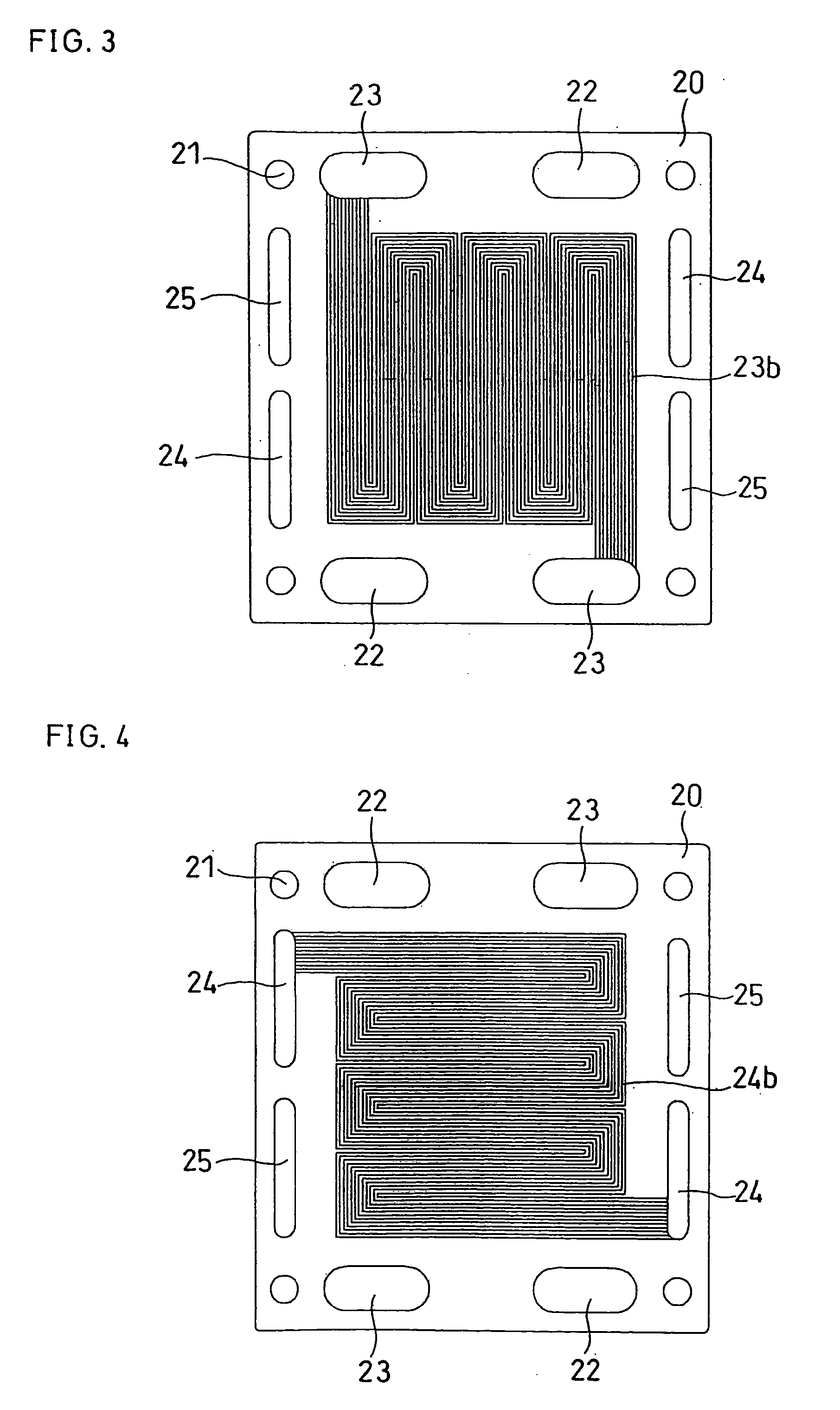
[0110] Using an isotopic graphite board, the anode-side separator plate shown in FIGS. 1 and 2 of Embodiment 1 and the cathode-side separator plate 20 shown in FIGS. 3 and 4 were produced by mechanical process. The separator plate had a thickness of 3 mm, and the grooves of the gas flow channels and the cooling water flow channels had a pitch length of 3 mm and a width of 1.5 mm.

[0111] (ii) Production of Sealing Member

[0112] The linear sealing member 30 and the flat sealing member 40, each having the same adhesive layer as that of Embodiment 1 shown in FIGS. 5 to 8, were produced.

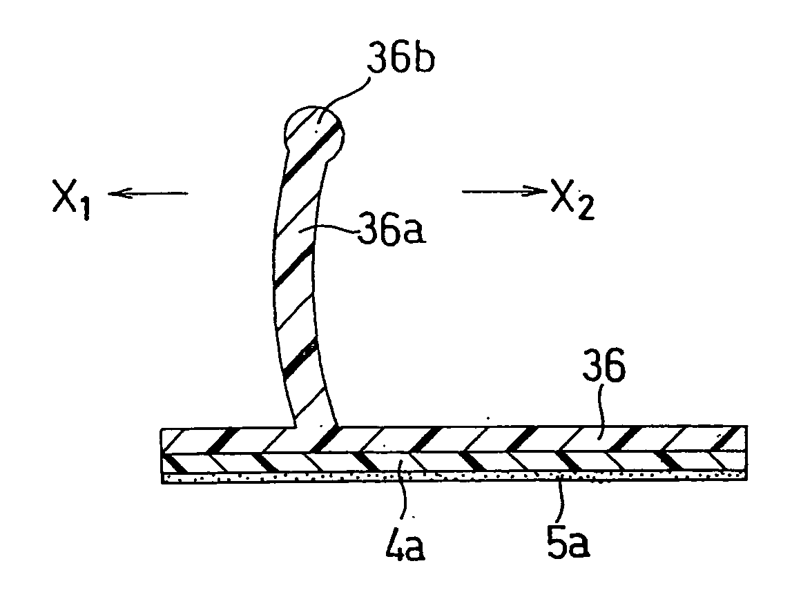
[0113] After placing polyimide films 4a and 4b with a thickness of 100 μm on a mold, the mold was cramped and fluorine rubber (“Viton”, fluorine rubber, manufactured by E.I. Du Pont de Nemours & Company Inc.) was projection-molded under conditions of a temperature of 200° C. and projection pressure of 150 kgf / cm2, to form the prescribed base sealing memb...

Example

COMPARATIVE EXAMPLE 1

[0129] A cell stack B was fabricated in the same manner as in Example 1 except for the use of a conventional flat gasket in place of the anode-side linear sealing member and the cathode-side flat sealing member used in Example 1. It is to be noted that a silicone-rubber-made sheet with a thickness of 75 μm was applied onto each face of a PET-made sheet with a thickness of 100 μm, and the resultant sheet was used as the flat gasket. Members were built using a jig for assembly in the same manner and procedure as in Example 1. Herein, the clearance between the flat gasket and the electrode was 0.25 mm both on the anode-side and the cathode side.

[0130] Cell B was subjected to the checking for gas leakage under the same conditions as in Example 1. Since a cramping load was 4000 kgf and the surface pressure applied to the MEA was 10 kgf / cm2, the stack was cramped at 4000 kgf. As a result, external leakage of the gas, and / or cross-leakage of the gas from the oxidant ...

Example

COMPARATIVE EXAMPLE 2

[0131] Cell C was fabricated in the same manner as in Comparative Example 1 except that the clearance between the flat gasket and the anode / cathode was 0.5 mm each. Members were built using a jig for assembly in the same manner and procedure as in Example 1.

[0132] Cell C was subjected to the checking for gas leakage under the same conditions as in Example 1. Since a cramping load was 4000 kgf and the surface pressure applied to the MEA was 10 kgf / cm2, the stack was cramped at 4000 kgf. As a result, there was observed no gas leakage on the oxidant side, the fuel gas side and the cooling water side, whereby it was confirmed that Cell C had no problem with a fluid sealing property.

[0133] After checking gas leakage, Cells A to C of Example 1 and Comparative Examples 1 and 2 were dissembled to confirm the building conditions thereof. In each of these cells, the anode of the MEA had been built slightly off the center of the anode-side linear sealing member; it was ...


PUM


Abstract

A polymer electrolyte fuel cell comprises an electrolyte membrane-electrode assembly, a pair of conductive separator plates sandwiching the electrolyte membrane of the electrolyte membrane-electrode assembly, and a pair of sealing means sealing between the electrodes of the electrolyte membrane-electrode assembly and the separator plates. The pair of sealing means is constituted by combination of a flat sealing member having a flat portion in flat contact with the electrolyte membrane and of a linear sealing member having a rib in linear contact with the electrolyte membrane, and at least part of the rib is in the form of falling in the direction to the electrode when the electrolyte membrane, the pair of electrodes and the pair of separator plates are stacked to be cramped. This makes it possible for the fuel cell to have an excellent sealing property and a stable output characteristic.

Description

BACKGROUND ART [0001] The present invention relates to a polymer electrolyte fuel cell for use in portable power sources, power sources for portable devices, power sources for electric vehicles, domestic cogeneration systems and the like. [0002] A fuel cell using a polymer electrolyte membrane electrochemically reacts a fuel gas containing hydrogen with an oxidant gas containing oxygen, such as air, to simultaneously generate electric power and heat. This fuel cell comprises a polymer electrolyte membrane for selectively transporting hydrogen ions, and a pair of electrodes, i.e. an anode and a cathode, formed respectively on both faces of the polymer electrolyte membrane. This is called an electrolyte membrane-electrode assembly (MEA). The electrode comprises: a catalyst layer mainly composed of a carbon powder carrying a platinum group metal catalyst and formed on each face of the polymer electrolyte membrane; and a gas diffusion layer formed on the outer surface of the catalyst la...

Claims


Application Information

Patent Timeline
IPC IPC(8): H01M8/02H01M8/10H01M8/24
CPCH01M8/0271H01M8/1004Y02E60/50H01M2300/0082H01M8/242H01M8/026H01M8/0263H01M8/0267H01M8/2483H01M8/02H01M8/10H01M8/24
Inventor OHARA, HIDEOMATSUMOTO, TOSHIHIROSHIBATA, SOICHISUGAWARA, YASUSHI
Owner PANASONIC CORP
Why Eureka
Try Eureka