[0016] One
advantage of the BLDC motor control locked and stopped
detector is that rotor detection is provided without requiring a rotor position or speed sensor or relying on an over-current detection circuit. Another
advantage of the present invention is that a commercially available, off-the-shelf motor control IC having a control input, for example, a current overload input port, may be utilized for switching on and off the driving of the phase coils and for most other aspects of motor control. Therefore, the present invention provides easy
interfacing with existing motor control systems and motor control ICs. Yet another
advantage of the present invention is that the fault detection circuit may include a
microcontroller that is enabled by
software, thus modifications to parameters and the control method can be easily made without hardware changes.
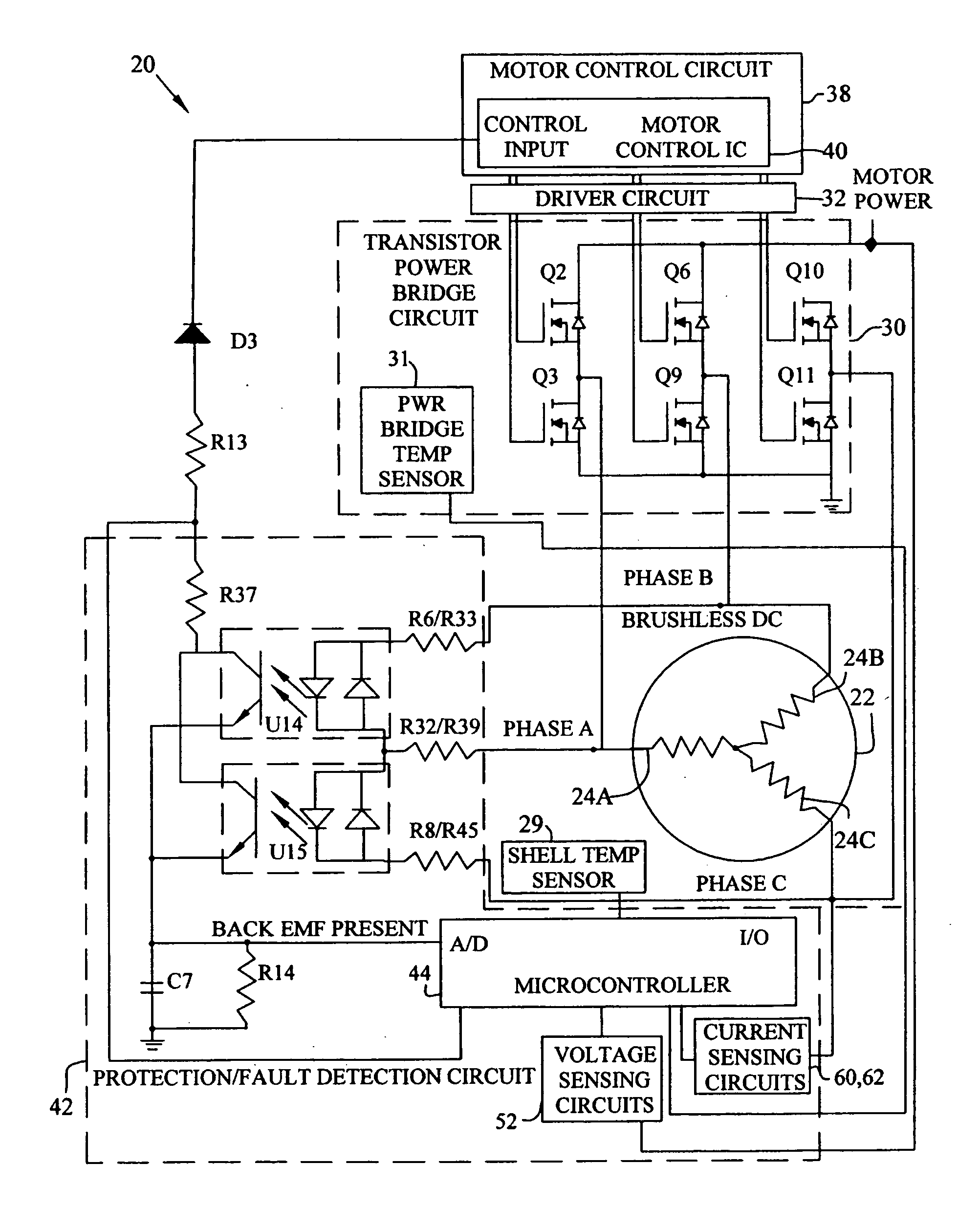
[0017] In one form, the present invention provides a motor
control system for controlling a brushless and sensorless DC
motor system having a plurality of phase coils, including: a motor control
integrated circuit having a plurality of motor driver outputs and a control input for operating the plurality of output drivers, the plurality of motor driver outputs coupled to the plurality of phase coils; and a fault detection circuit coupled with the control input and capable of electively switching the state of said
control signal to momentarily disable said plurality of out put drivers, said fault detection circuit is coupled to at least one of the plurality of phase coils and is capable of detecting a threshold back EMF
voltage from the at least one of the plurality of phase coils.
[0018] In another form, the present invention provides a motor
control system for controlling a brushless and sensorless DC
motor system having a plurality of phase coils, including: a motor control integrated circuit having a plurality of motor driver outputs and a control input for operating the plurality of output drivers, said plurality of motor driver outputs coupled to the plurality of phase coils; and a fault detection circuit coupled with the control input and capable of detecting a plurality of electrical and nonelectrical fault conditions of the
motor system, the fault detection circuit capable of providing a
control signal to the control input to disable the plurality of output drivers upon detection of at least one of the plurality of electrical and nonelectrical fault conditions.
[0019] In another form, the present invention provides a method for detecting faults in a motor control system for a brushless and sensorless DC motor system having a plurality of phase coils, including the steps of: providing a motor control integrated circuit having a plurality of power drivers coupled to the plurality of phase coils, and having a control input capable of selectively enabling the plurality of power drivers; detecting a motor system fault by measuring EMF on at least on of the plurailty of phase coils; and switching the control input to disable the plurality of power drivers upon detecting a motor system fault, indicated by measured EMF below a present threshold thereby stopping motor operation.
[0020] In yet another form, the present invention provides a method for detecting a locked or stopped rotor in a motor control system for a brushless and sensorless DC motor system having a plurality of phase coils driven by power drivers, including the steps of: disabling the power drivers; then measuring the back EMF generated from the plurality of phase coils; and then enabling the power drivers after a time period dependent on the measured back EMF.
[0021] In another form, the present invention provides a
fluid handling system, including: a pump; a brushless DC motor for driving the pump, the motor having a plurality of phase coils; and a motor control system coupled to the motor, the
motor controller system including: a motor
control circuit having at least one motor driver output coupled to the plurality of phase coils; and a
microcontroller having an A / D converter coupled to at least one of the plurality of phase coils and having
software enabling the micocontroller to provide an output
signal coupled to the motor
control circuit momentarily disabling the at least one motor driver output, the
microcontroller capable of measuring a
voltage level of back EMF generated in at least one of the plurality of phase coils upon the at least one motor driver output being disabled.

