Exposure apparatus

a technology of exposure apparatus and uv light, which is applied in the direction of photomechanical apparatus, instruments, printing, etc., can solve the problems of inability to create a high vacuum, inability to use refractive optical system (that utilizes lens or light refraction) for visual light and uv light, and inability to achieve high vacuum, stably perform exposure, and prevent diffusion

Inactive Publication Date: 2005-02-10
CANON KK
View PDF5 Cites 33 Cited by
  • Summary
  • Abstract
  • Description
  • Claims
  • Application Information

AI Technical Summary

Benefits of technology

[0013] Accordingly, it is an exemplary object of the present invention to provide an exposure apparatus that can stably per...

Problems solved by technology

However, lithography using ultraviolet light has limitations when it comes to satisfying the rapidly promoted fine processing of a semiconductor device.
Since materials greatly absorb the light of a wave range of the EUV light, a refractive optical system (that utilizes lenses or refractions of light) for use with visual light and UV light is not viable because of the low transmittance of the EUV light to an optical element, such as a lens.
Therefore, as for the wafer stage, crea...

Method used


Image

  • Exposure apparatus
  • Exposure apparatus
  • Exposure apparatus

Examples


Embodiment Construction

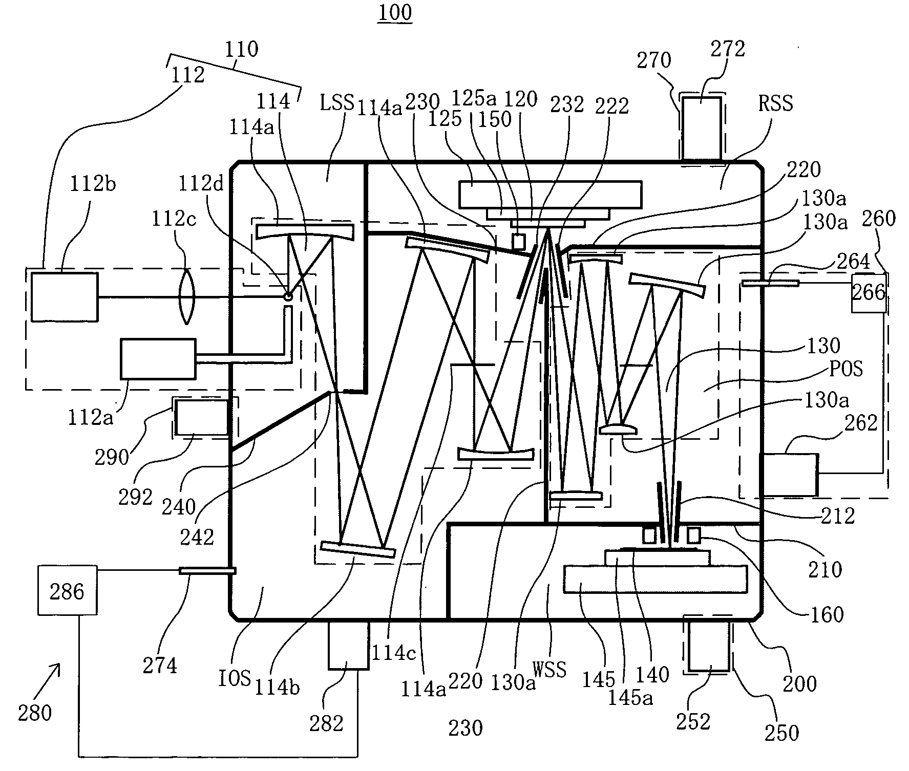
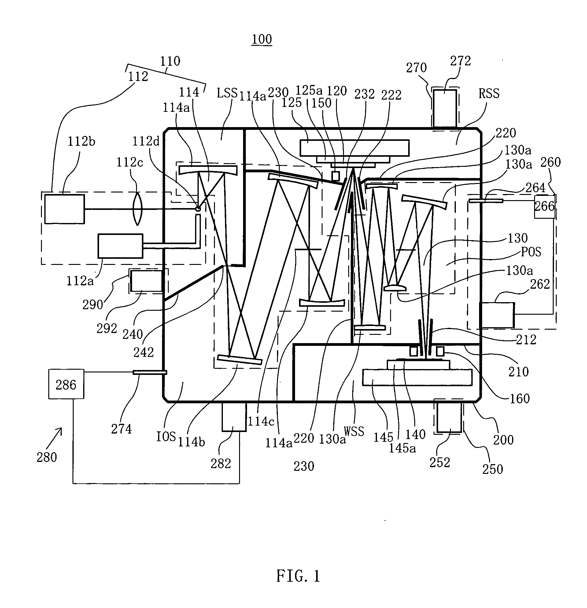
[0025] With reference to the accompanying drawings, a description will be given of an exposure apparatus of one embodiment according to the present invention. In each figure, the same reference numeral denotes the same element. Therefore, duplicate descriptions will be omitted. Here, FIG. 1 is a schematic sectional view of an exposure apparatus 100 as one aspect according to the present invention.

[0026] The inventive exposure apparatus 100 is a projection exposure apparatus that uses, as illumination light for exposure, EUV light (e.g., with a wavelength of 13.4 nm) to perform a step-and-scan or step-and-repeat exposure that transfers a circuit pattern on a reticle 120 onto an object 140 to be exposed. Such an exposure apparatus is suitably applicable to a lithography process below submicron or quarter-micron, and a description will be given below of this embodiment exemplarily using a step-and-scan exposure apparatus (which is also called “a scanner”). The step-and-scan manner, as...


PUM


Abstract

An exposure apparatus for exposing an object put on a first stage by irradiating light from a light source onto the object through an exposure optical system includes a partition for isolating a first space where the first stage is arranged and isolating a second space where the exposure optical system is arranged, a first management part that manages a degree of vacuum of the first space, and a second management part that manages a degree of vacuum of the second space.

Description

[0001] This application claims foreign priority benefits based on Japanese Patent Applications No. 2003-288438, filed on Aug. 7, 2003, which is hereby incorporated by reference herein in its entirety as if fully set forth herein. BACKGROUND OF THE INVENTION [0002] The present invention relates to an exposure apparatus, and more particularly to an exposure apparatus that exposes an object, such as a single crystal substrate and a glass plate for a liquid crystal display (“LCD”). The present invention is suitable, for example, for an exposure apparatus that uses extreme ultraviolet (“EUV”) light for an exposure light source. [0003] Conventionally, during manufacturing, photolithography technology, a reduction projection exposure apparatus using a projection optical system to project a circuit pattern formed on a reticle (mask) onto a wafer, etc., has been employed for transferring the circuit pattern of fine semiconductor devices such as semiconductor memory and logic circuit. [0004] ...

Claims


Application Information

Patent Timeline
IPC IPC(8): G03B27/42G03F7/20H01L21/027
CPCG03B27/42G03F7/70841G03F7/70808
Inventor TERASHIMA, SHIGERUHASEGAWA, NORIYASU
Owner CANON KK
Why Eureka
Try Eureka