
Mass spectrometer interface

Active Publication Date: 2005-02-17
PERKINELMER SCI CANADA ULC
View PDF16 Cites 36 Cited by
  • Summary
  • Abstract
  • Description
  • Claims
  • Application Information

AI Technical Summary

Benefits of technology

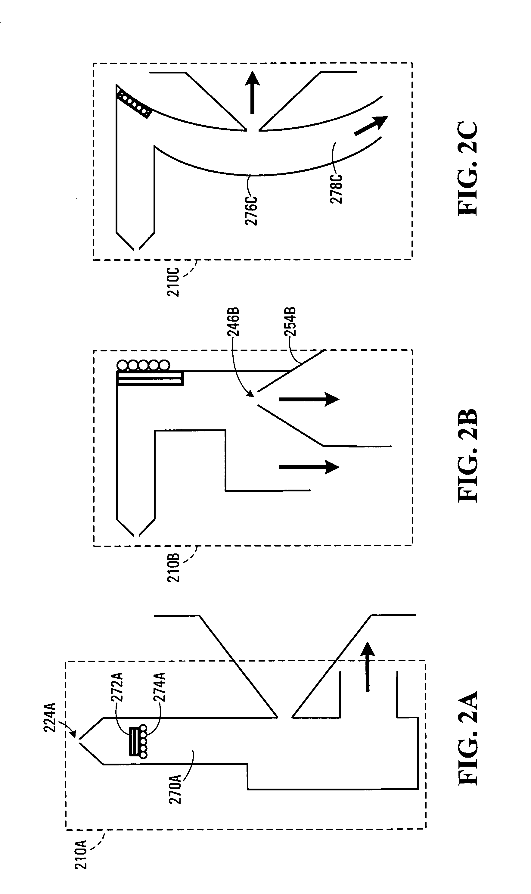
[0014] Accordingly, in an aspect of the present invention, there is provided a method of supplying ionized particles (having characteristic mass to charge (m / z) ratios) of a sample to a mass spectrometer. The method includes providing a tortuous flow of gas having at least one region of disturbance, to transport the ionized particles. A first mixture of the ionized particles and any attached impurities is introduced into the flow to allow the ionized particles to collide in the region of disturbance. Thermal energy is added proximate the region of disturbance to promote liberation of at least some of the ionized particles from the impurities, thereby increasing the concentration of the ionized particles having the characteristic m / z ratios in the flow.
[0020] In another aspect of the present invention, an apparatus for providing ionized particles (having characteristic mass to charge (m / z) ratios) of a target sample to a mass spectrometer includes a channel for guiding a flow of gas along a tortuous path creating at least one region of disturbance in the flow, the region of disturbance for colliding a mixture of ionized particles and any attached impurities to liberate at least some of the ionized particles from the impurities, thereby increasing the concentration of the ionized particles having the characteristic m / z ratios in said flow.
[0021] Advantageously, embodiments of the invention provide a high signal-to-noise ratio, with increased sensitivity and reduced chemical background, particularly using high liquid flow rates, by improving the efficiency of liberating attached impurities such as cluster molecules, atoms, ions or adducts.

Problems solved by technology

Doing this efficiently presents numerous challenges.
Disadvantageously, API sources produce high chemical background and relatively low sensitivity.
This results in a poor signal-to-noise ratio.
Many solvated droplets enter into the mass spectrometer and consequently produce a large level of chemical noise across the entire mass range.
Additionally incompletely vaporized droplets linger near the sampling orifice.
These problems can be most severe for high flow rates.
Another problem with electrospray concerns the condensation of the expanding jet and clustering of the ions.
This approach has several negative side effects, including: a) restricting the time for ion desolvation, b) enhancing ion salvation, c) restricting the gas flow through the orifice due to pumping requirements and the spatial requirements of sampling a free jet expansion.
While the counter flow of gas results in some improvement in sensitivity for low liquid flow rates, it is insufficient for high liquid flow rates, for example 10 microliters per minute or more, where substantially more energy transfer is required than the counter flow of gas can provide.
Also, even for low liquid flow rates, it substantially increases the complexity of the interface between the electrospray and the mass spectrometer.
High gas flow rates may prevent some ions with low mobility from entering the analyzer, while low gas flow rates or reduced gas temperature may not sufficiently desolvate the ions.
Accordingly, much trial and error time is necessary to determine the optimum gas flow rate and temperature for each particular analyte utilizing a particular electrospray device and a particular mass spectrometer.
Accordingly, this reduced transfer of ions to the mass analyzer produced by electrospray substantially limits the sensitivity and the signal-to-noise ratio of the electrospray / mass spectrometer technique.
This design suffers from incomplete desolvation due to low residence time in the chamber, and compromises sensitivity due to scattering losses.
This design yields increased complexity and cost of an additional pumping stage following the initial expansion.

Method used


Image

  • Mass spectrometer interface
  • Mass spectrometer interface
  • Mass spectrometer interface

Examples


Embodiment Construction

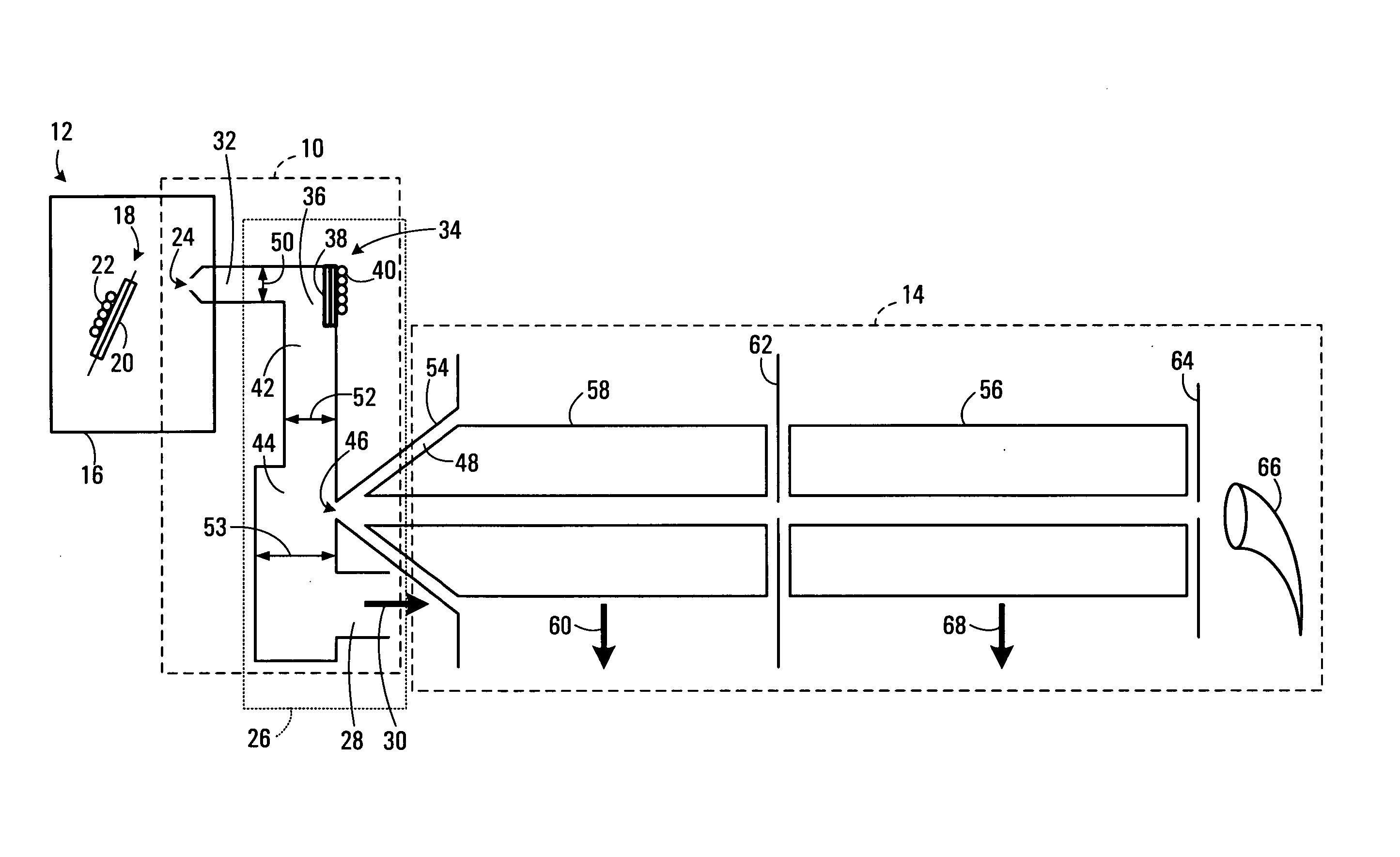
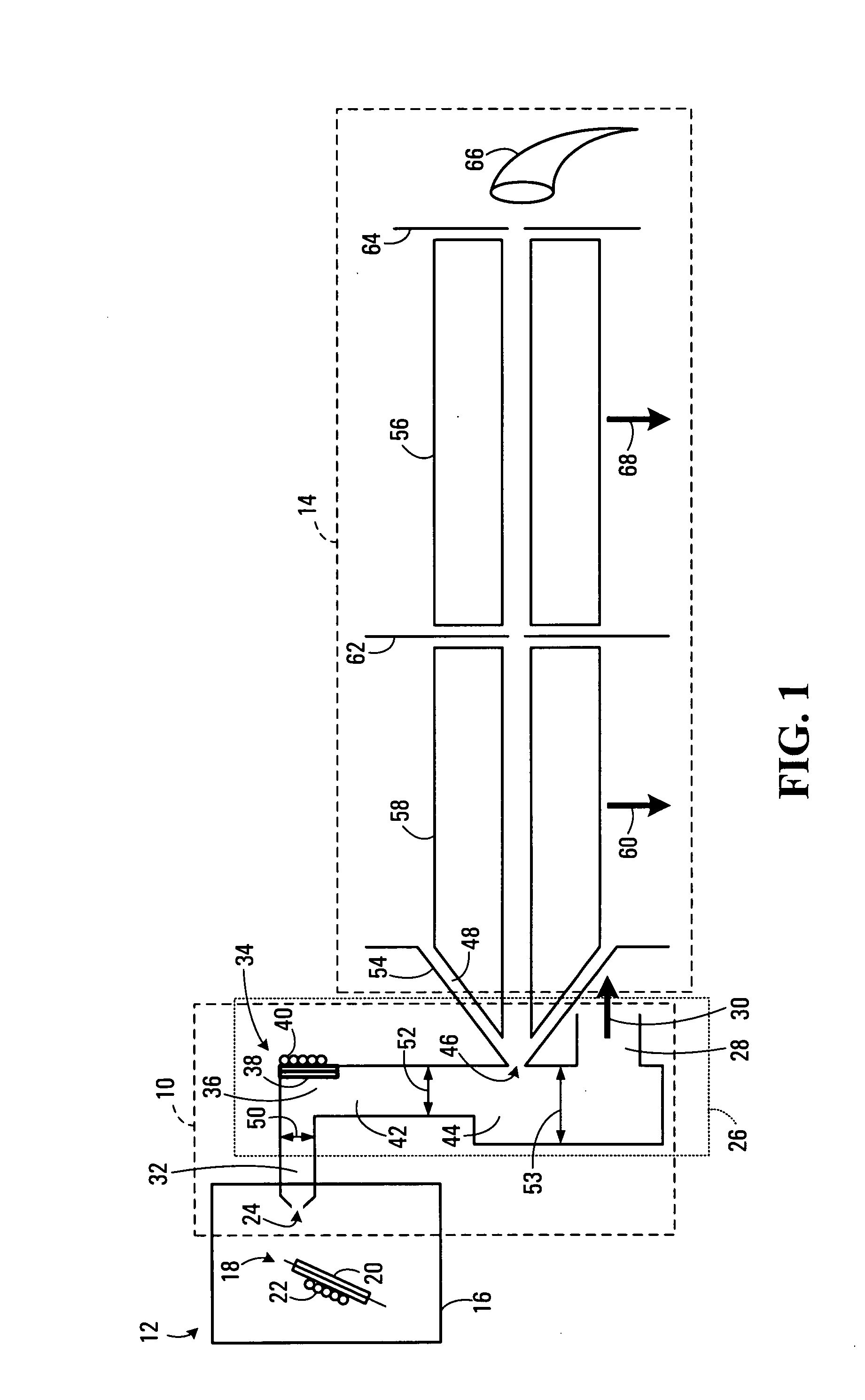
[0034] An exemplary embodiment of a mass spectrometer interface 10 is illustrated in FIG. 1. As illustrated, mass spectrometer interface 10 couples an atmospheric pressure ion source 12 and a mass spectrometer 14 in such a way as to enhance concentration, or sensitivity, of ions of characteristic m / z and reduce chemical background while providing the appropriate gas flow to a mass spectrometer system.

[0035] Atmospheric pressure ion source 12 is enclosed in a chamber 16 that is maintained at approximately atmospheric pressure. In the exemplary embodiment, ion source 12 is shown as electrospray, but may be an ion spray, a MALDI, a corona discharge device, an atmospheric pressure chemical ionization device, an atmospheric pressure photo ionization device, or any other known ion source.

[0036] A trace substance to be analyzed is ionized by electrospray ionization using a needle 18 or other ionizing means, in a conventional manner. Samples injected into ion source 12 elute in a flow of ...


PUM


Abstract

A mass spectrometer interface, having improved sensitivity and reduced chemical background, is disclosed. The mass spectrometer interface provides improved desolvation, chemical selectivity and ion transport. A flow of partially solvated ions is transported along a tortuous path into a region of disturbance of flow, where ions and neutral molecules collide and mix. Thermal energy is applied to the region of disturbance to promote liberation of at least some of the ionized particles from any attached impurities, thereby increasing the concentration of the ionized particles having the characteristic m / z ratios in the flow. Molecular reactions and low pressure ionization methods can also be performed for selective removal or enhancement of particular ions.

Description

[0001] This application claims the benefit of U.S. Provisional Patent Application No. 60 / 476,631 filed on Jun. 9, 2003, which is hereby incorporated by reference in its entirety.FIELD OF THE INVENTION [0002] The present invention relates generally to mass spectrometry and more particularly to an interface for providing particles to a mass spectrometer, and to a mass spectrometry apparatus including the interface, and related methods. BACKGROUND OF THE INVENTION [0003] Mass spectrometry (MS) is a well-known technique of obtaining a molecular weight and structural information about chemical compounds. Using mass spectrometry techniques, molecules may be weighed by ionizing the molecules and measuring the response of their trajectories in a vacuum to electric and magnetic fields. Ions are weighed according to their mass-to-charge (m / z) values. [0004] Atmospheric pressure ion sources (API) have become increasingly important as a means for generating ions used in mass spectrometers. Some...

Claims


Application Information

Patent Timeline
IPC IPC(8): H01J49/04H01J49/26H01J49/42
CPCH01J49/0468Y10T436/24H01J49/04H01J49/06H01J49/044H01J49/0422H01J49/26
Inventor JOLLIFFE, CHARLESJAVAHERY, GHOLAMREZACOUSINS, LISA
Owner PERKINELMER SCI CANADA ULC
Learn More