Method and electromagnetic sensor for measuring partial discharges in windings of electrical devices

Inactive Publication Date: 2005-02-17
ALSTOM TECH LTD
View PDF9 Cites 39 Cited by
  • Summary
  • Abstract
  • Description
  • Claims
  • Application Information

AI Technical Summary

Benefits of technology

Therefore, it is an object of the present invention to provide an improved measuring method, which avoids the stated drawbacks of the prior art. The improved measuring method should provide more information about the status of the insulation system by using non-destructi

Problems solved by technology

Partial discharges, that can lead to breakdowns in the insulating system, are caused by high internal stresses, mainly induced by 50/60 Hz voltages, as well as by high frequency electromagnetic fields due to lightning pulses, connection transients etc.
Generally, these impulsive stresses are not uniformly distributed along the stator winding, but are located within the first turns connected to the high-voltage source, so they can principally induce failures in the turn and/or conductor insulation of the winding, that may lead then to the ground insulation yielding.
These damages induced by such impulsive stresses are even more severe if frequency converters are interposed between the electrical machine and the network, in particular if pulse width modulated (PWM) inverter fed motors are considered.
Often the applied surge voltages cause damages in some insulation areas owing to the low sensitivity of this technique.
There are even more disadvantages in that method used up to now, as e.g. the need to induce a clear short-circuit, and the lack of measuring a value related to the condition of the turn or conductor insulation of the respective winding.
Major drawbacks of the known measuring techniques are that they do not provide an absolute measurement, i.e. they only allow damage recognition by means of a comparative method and therefore can not be used if only one probe is available at a time.
Further, the known measuring techniques provide only information on the presence of possible s

Method used


Image

  • Method and electromagnetic sensor for measuring partial discharges in windings of electrical devices
  • Method and electromagnetic sensor for measuring partial discharges in windings of electrical devices
  • Method and electromagnetic sensor for measuring partial discharges in windings of electrical devices

Examples


Embodiment Construction

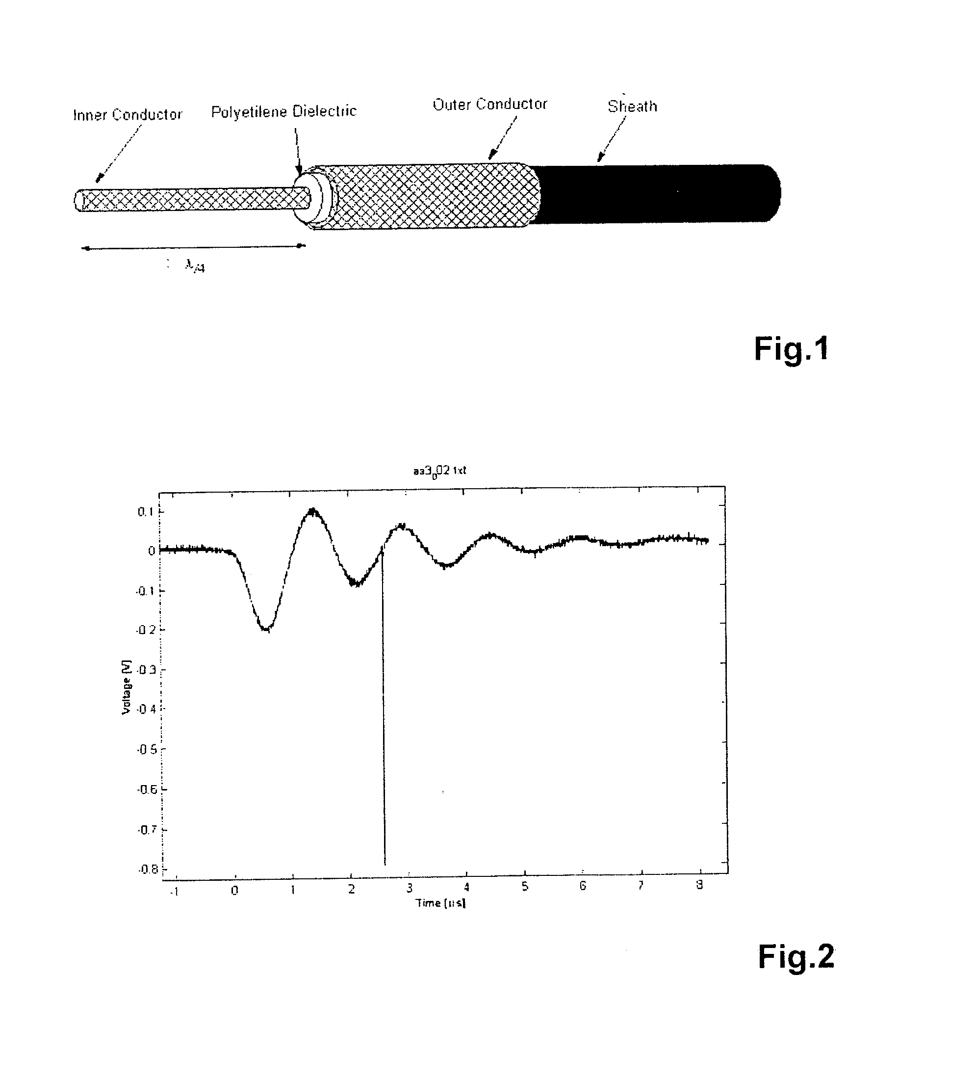
One preferred embodiment of the electromagnetic sensor according to the present invention is schematically shown in FIG. 1. According to this embodiment, the electromagnetic sensor is obtained from an usual BNC coaxial cable, the latter consists of an inner conductor which is surrounded by a polyethylene dielectric which is entirely surrounded by a sheath material. The sheath material is surrounded by an outer conductor and coated with a (non shown) tube material, e.g. polyvinylchloride. To get the electromagnetic sensor according to the preferred embodiment of the present invention, as sketched in FIG. 1, the inner conductor is freed for a defined length l and the outer conductor can be cut off or simply turned inside out and stuck on the protective tube of the BNC cable. The free length of the inner conductor is directly related to the tuned frequency to be measured and can be calculated according to the formula:

l=λ / 4.

wherein l=length of the freed inner conductor and λ=wavelengt...


PUM


Abstract

A method for measuring partial discharges in windings of electrical devices comprised by the following steps: Applying voltages having high frequency components to the winding of the electrical device, detecting partial discharge signals by means of a tuned VHF and/or UHF electromagnetic sensor located close to the electrical device and evaluating the detected sensor signals by means of electrical hardware or software. Further, a VHF and/or UHF electromagnetic sensor for measuring partial discharges in windings of electrical devices is described wherein an antenna made of a coaxial cable is provided as electromagnetic sensor. The present invention provides an improved measuring method and sensor device, which avoid the drawbacks of the prior art. The improved measuring method provides more detailed information about the status of the insulation system and clear short-circuits during the testing are not necessary any more. The proposed sensor provides a surprisingly simple and inexpensive solution.

Description

TECHNICAL FIELD The invention refers to a method and an electromagnetic sensor for measuring partial discharges (PD) in windings of electrical devices, e.g. electrical generators and motors, particularly in stators and / or rotors, stressed by voltage sources having high frequency (surge) components. RELATED PRIOR ART Methods and sensors for measuring partial discharges in windings of electrical devices, e.g. Ac or Dc electrical generators and motors, are already known in the prior art. These devices are generally fed by power networks at industrial frequencies of either 50 or 60 Hz. Currently both, couplers and electromagnetic sensors available on the market, are broadly used for partial discharge measurements. These measuring devices are either capacitors appropriately placed within the electric machine or outwardly. In addition, in some cases high frequency sensors are located in the stator slots. Partial discharges, that can lead to breakdowns in the insulating system, are caus...

Claims


Application Information

Patent Timeline
IPC IPC(8): G01R31/06G01R31/34
CPCG01R31/027G01R31/346G01R31/1227G01R31/62
Inventor RABACH, GERMANOVISINTIN, MASSIMILIANO
Owner ALSTOM TECH LTD
Why Eureka
Try Eureka