
Laser irradiation method, method for manufacturing a semiconductor device, and a semiconductor device

a laser irradiation and semiconductor technology, applied in the direction of semiconductor/solid-state device testing/measurement, radiofrequency controlled devices, instruments, etc., can solve the problem that the incident light on the semiconductor film interferes with the reflected light from the second surface, so as to improve the uniformity of annealing, and reduce the effect of laser beam transmittan

Inactive Publication Date: 2005-02-17
SEMICON ENERGY LAB CO LTD
View PDF25 Cites 9 Cited by
  • Summary
  • Abstract
  • Description
  • Claims
  • Application Information

AI Technical Summary

Benefits of technology

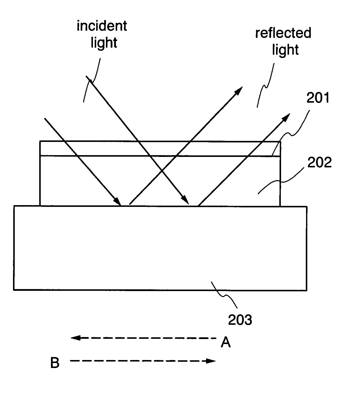
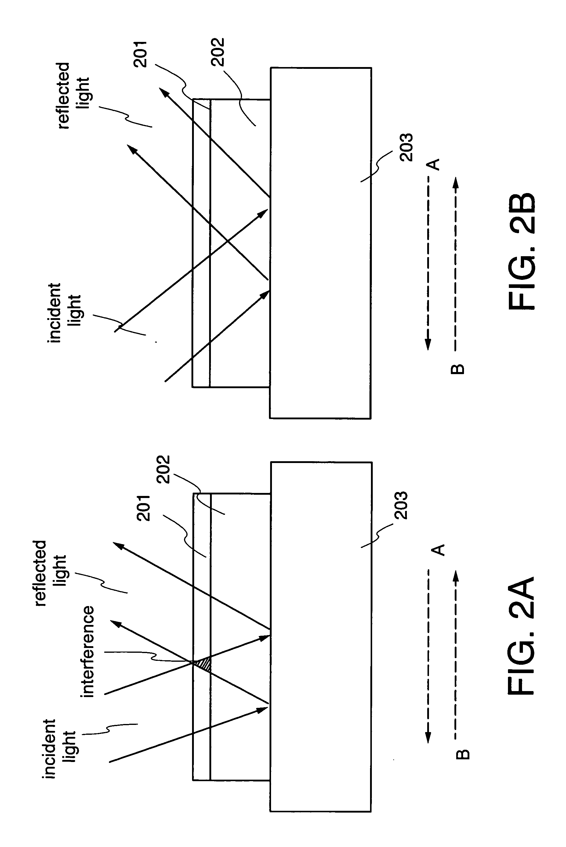
[0027] When the laser annealing is performed according to the present invention, the laser beam is reflected on the first surface of the substrate; or the laser beam is absorbed in the substrate; or the laser beam is partially reflected on the first surface thereof and partially absorbed therein. Therefore, when the reflected light from the second surface of the substrate has the intensity lower than the threshold at which the intensity of the reflected light affects the state of the semiconductor film to be annealed, the uniformity of the annealing can be improved. And, when the substrate opaque to the laser beam is used in the laser annealing, the transmittance of the laser beam becomes small. Therefore, when the laser beam is incident into the substrate, the incident light does not reach the second surface of the substrate, thereby not producing the reflected light from the second surface of the substrate. For this reason, the uniformity of the annealing can be improved, and it is no longer necessary to consider the effect of the reflected light from the second surface of the substrate in the laser annealing.
[0028] Moreover, the effect of the reflected light from the second surface of the substrate can be suppressed with the laser beam can be made incident vertically into the semiconductor film. When the laser beam can be incident vertically, the optical design can have large degree of freedom. For example, a beam homogenizer such as a diffractive optic can be used to form a laser beam having uniform intensity distribution easily. In addition, according to the present invention, the reflected light from the second surface of the substrate hardly affects or does not affect at all even though the laser beam having the uniform intensity distribution is incident vertically into the substrate. Therefore, uniformity of the crystallinity of the semiconductor film annealed by the laser beam can be considerably improved. On this occasion, when the CW laser oscillator having a wavelength in the visible region such as an emission wavelength of an Ar laser or a second harmonic of a YVO4 laser is used, the whole surface of the semiconductor film can be crystallized to obtain a large crystal grain region in a comparatively short period of time because the energy absorption coefficient is higher than the other wavelengthes. In addition, when TFTs are manufactured using the semiconductor film, the mobility increases remarkably compared with TFTs that manufactured using the conventional crystalline semiconductor film. Therefore, the TFT manufactured by the present invention can be also used to the semiconductor device requiring the high-speed operation.
[0029] Moreover, since the present invention can make the laser beam incident into the substrate vertically, the semiconductor film can be annealed uniformly not depending on the scanning direction. The same large crystal grain region can be obtained by scanning the laser beam back and forth, thereby being able to process many substrates in a short period of time. That is to say, an advantage of high throughput can be obtained.

Problems solved by technology

On this occasion, since the reflected light from the second surface of the substrate is incident into the semiconductor film heated and melted by the incident light, the reflected light form the second surface interferes with the incident light on the semiconductor film.

Method used


Image

  • Laser irradiation method, method for manufacturing a semiconductor device, and a semiconductor device
  • Laser irradiation method, method for manufacturing a semiconductor device, and a semiconductor device
  • Laser irradiation method, method for manufacturing a semiconductor device, and a semiconductor device

Examples


embodiment 1

[0035]FIGS. 4A and 4B are drawings for explaining a thin film chip in an embodiment 1;

[0036]FIGS. 5A and 5B are drawings for explaining how to mount the thin film chip on the substrate with the pixel portion formed thereon in an embodiment 1;

embodiment 2

[0037]FIG. 6 is a drawing for explaining a CPU in an embodiment 2; and

[0038]FIG. 7 is a drawing for explaining an embodiment mode 2.

embodiment

[0039] (Embodiment Mode 1)

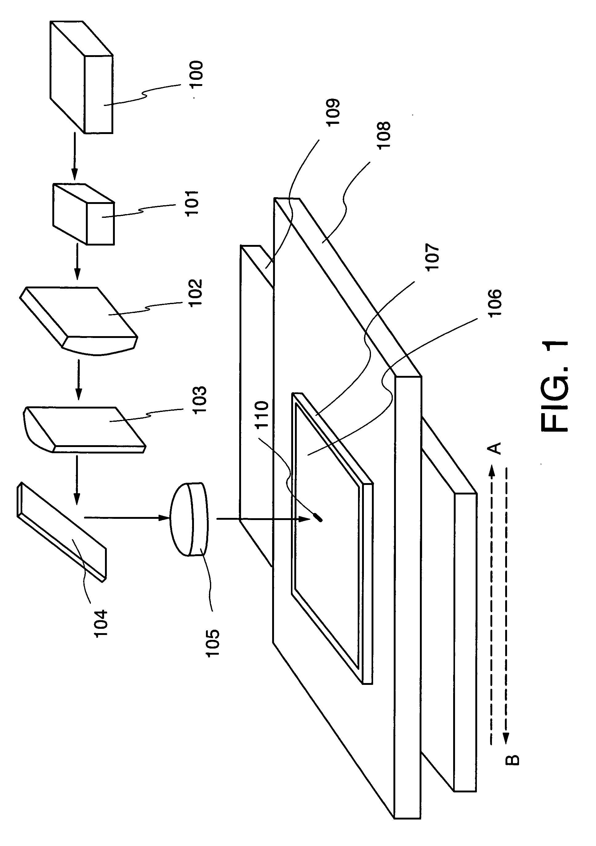
[0040] The embodiment mode 1 of the present invention is explained in detail with reference to FIGS. 1 and 3.

[0041] Initially, impurities are mixed into a glass substrate to form a colored glass substrate that is opaque to the visible light. Then, an amorphous semiconductor film or a non-single crystal semiconductor film is formed over the colored glass substrate, and the laser annealing is performed to the colored glass substrate as the irradiated surface. It is noted that not only the colored glass substrate, but also another substrate such as a ceramic substrate made of the material that is opaque to the laser beam to be irradiated and that can resist the heat in the laser annealing can be used as the substrate.

[0042] Next, a laser irradiation method is explained with reference to FIG. 1. In FIG. 1, the laser beam propagates in a direction indicated by arrows of continuous lines. A laser oscillator 100 is a YVO4 laser emitting a second harmonic light. ...


PUM

PropertyMeasurementUnit
lengthaaaaaaaaaa
temperatureaaaaaaaaaa
reflectivityaaaaaaaaaa

Abstract

The present invention discloses the semiconductor device having the substrate that reflects the laser beam on a surface; that absorbs the laser beam therein; or that partially reflects the laser beam on the surface and partially absorbs the laser beam in the laser annealing. Moreover, the substrate has a poly-crystalline semiconductor film having a large grain size. The present invention suppresses the effect due to the reflected light from a rear surface of the substrate and therefore the uniform laser annealing can be performed.

Description

BACKGROUND OF THE INVENTION [0001] 1. Field of the Invention [0002] The present invention relates to a semiconductor device where an element such as a transistor is formed using a semiconductor film formed over a substrate. Moreover, the present invention relates to a laser irradiation method for annealing the semiconductor film for example. Furthermore, the present invention relates to a method for manufacturing a semiconductor device including the laser irradiation in its step. [0003] 2. Related Art [0004] In recent years, a technique to form a thin film transistor (hereinafter referred to as a TFT) over a substrate has made great progress and application development to an active matrix display device has been advanced. Particularly, TFTs formed using poly-crystalline semiconductor films are superior in field-effect mobility to TFTs formed using conventional amorphous semiconductor films, and therefore high-speed operation becomes possible. For this reason, a circuit for driving p...

Claims


Application Information

Patent Timeline
Patent Type & Authority Applications(United States)
IPC IPC(8): B23K26/06B23K26/08H01L21/20H01L21/268H01L21/336H01L29/786
CPCB23K26/0639B23K26/0648B23K26/0665H01L29/78675H01L21/2026H01L21/268H01L29/66757B23K26/0853B23K26/064H01L21/02686H01L21/02683H01L21/02422H01L21/02678H01L21/02532H01L21/0242H01L21/02595H01L21/02691H01L21/02675
Inventor TANAKA, KOICHIRO
Owner SEMICON ENERGY LAB CO LTD
Learn More