Nanocomposite magnet and method for producing the same

a nano-composite magnet and nano-composite technology, applied in the field of nano-composite magnets, can solve the problems of hard ferrite magnets not being able to achieve the high remanence bsub>, the cost of sm-co-based magnets is high, and the cost of producing nd-fe-b-based magnets is still high, so as to increase the magnetization of nano-composite magnets, improve the performance of nano-

Inactive Publication Date: 2005-02-24
SUMITOMO SPECIAL METAL CO LTD
View PDF14 Cites 27 Cited by
  • Summary
  • Abstract
  • Description
  • Claims
  • Application Information

AI Technical Summary

Benefits of technology

The additive Ti achieves these advantageous effects. However, the present inventors discovered that if the mole fraction of the rare-earth elements was reduced to further increase the magnetization of the nanocomposite magnet disclosed in Japanese Laid-Open Publication No. 2002-175908, the magnet performance rather deteriorated. To increase the magnetization of a nanocomposite magnet in which the hard magnetic phase having the R2Fe14B type crystal structure and the soft magnetic phases such as the α-Fe and iron-based borides coexist in the same metal structure and are magnetically coupled together through exchange interactions, it is normally believed effective to decrease the mole fraction of the rare-earth elements and thereby increase the volume percentage of the α-Fe phase. This is because the saturation magnetization of the α-Fe phase is higher than that of the hard magnetic phase having the R2Fe14B type crystal structure.
However, the present inventors discovered that if the mole fraction of the rare-earth elements, included in a composition with Ti, was reduced to about 7 at % or less, a coercivity HcJ of about 400 kA/m or more could not be achieved, the demagnetization curve had bad loop squareness, and good magnetic properties were not obtained unless the amount of the additive Ti was increased. Nevertheless, when the amount of the additive Ti was simply increased to overcome such a problem, a non-magnetic Ti—B compound precipitated profusely and the magnet performance rather deteriorated.
Thus, the present inventors carried out experiments in which various combinations of metal elements, each consisting of Ti and another metal element, were added to a composition in which the mole fraction of the rare-earth elements was reduced to about 7 at % or less and boron was included at an increased mole fraction. As a result, when Ti and V were added in combination, a nanocomposite magnet, including increased volume percentages of iron-based borides and α-Fe with high magnetization, could be produced successfully by a strip casting

Problems solved by technology

However, the hard ferrite magnets cannot achieve the high remanence Br of 0.5 T or more.
However, the Sm—Co based magnet is expensive, because Sm and Co are both expensive materials.
Nevertheless, it is still expensive to produce the Nd—Fe—B based magnet.
Also, a powder metallurgical process normally requires a relatively large number of manufacturing and processing steps by its nature.
However, the only known effective method of improving the remanence Br is increasing the density of the bonded magnet.
However, none of these proposed techniques is reliable enough to always obtain a sufficient “characteristic value per cost”.
More specifically, none of the nanocomposite magnets produced by these techniques realizes a coercivity that is high enough to actually use it in various applications.
Thus, none of these magnets can exhibit commercially viable magnetic properties.
However, if the mole fraction of the rare-earth elements

Method used


Image

  • Nanocomposite magnet and method for producing the same
  • Nanocomposite magnet and method for producing the same
  • Nanocomposite magnet and method for producing the same

Examples


example 1

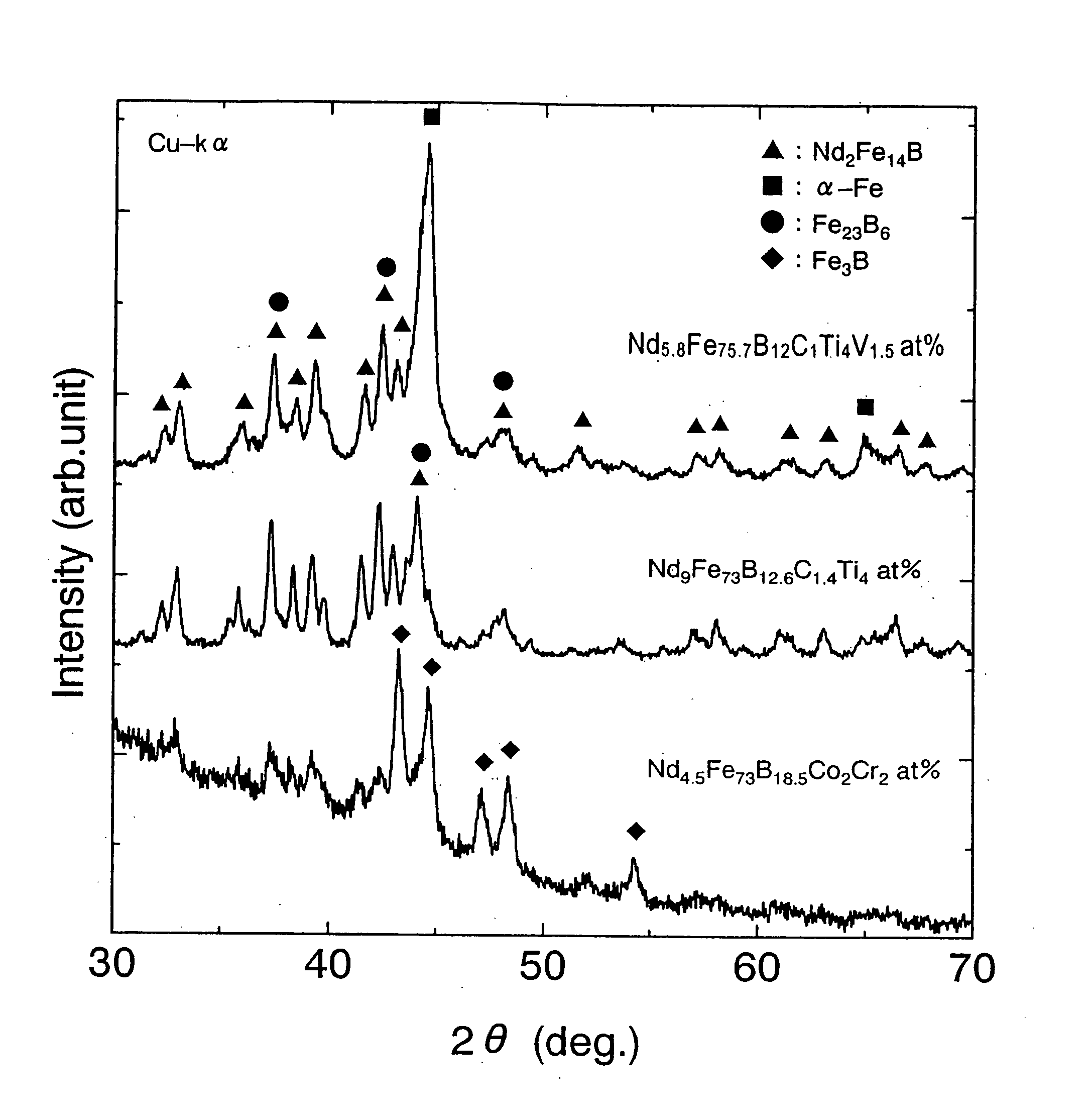
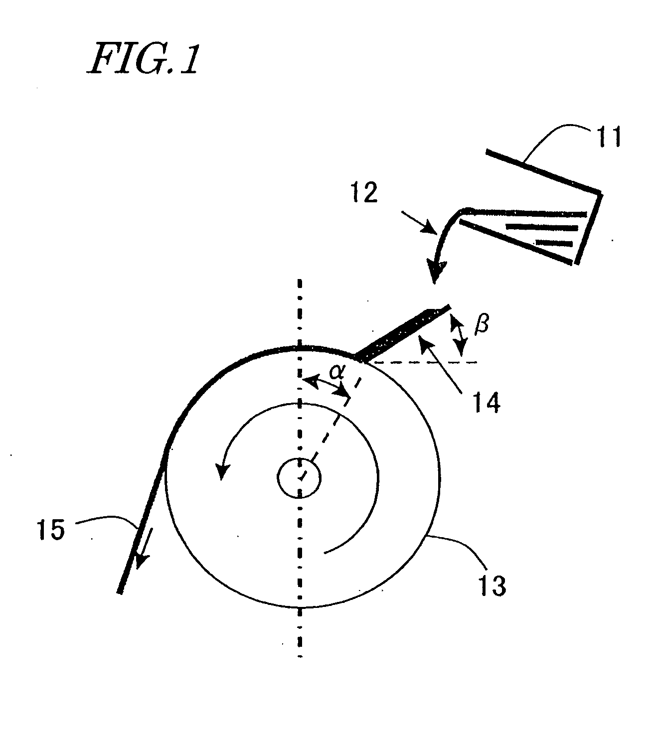
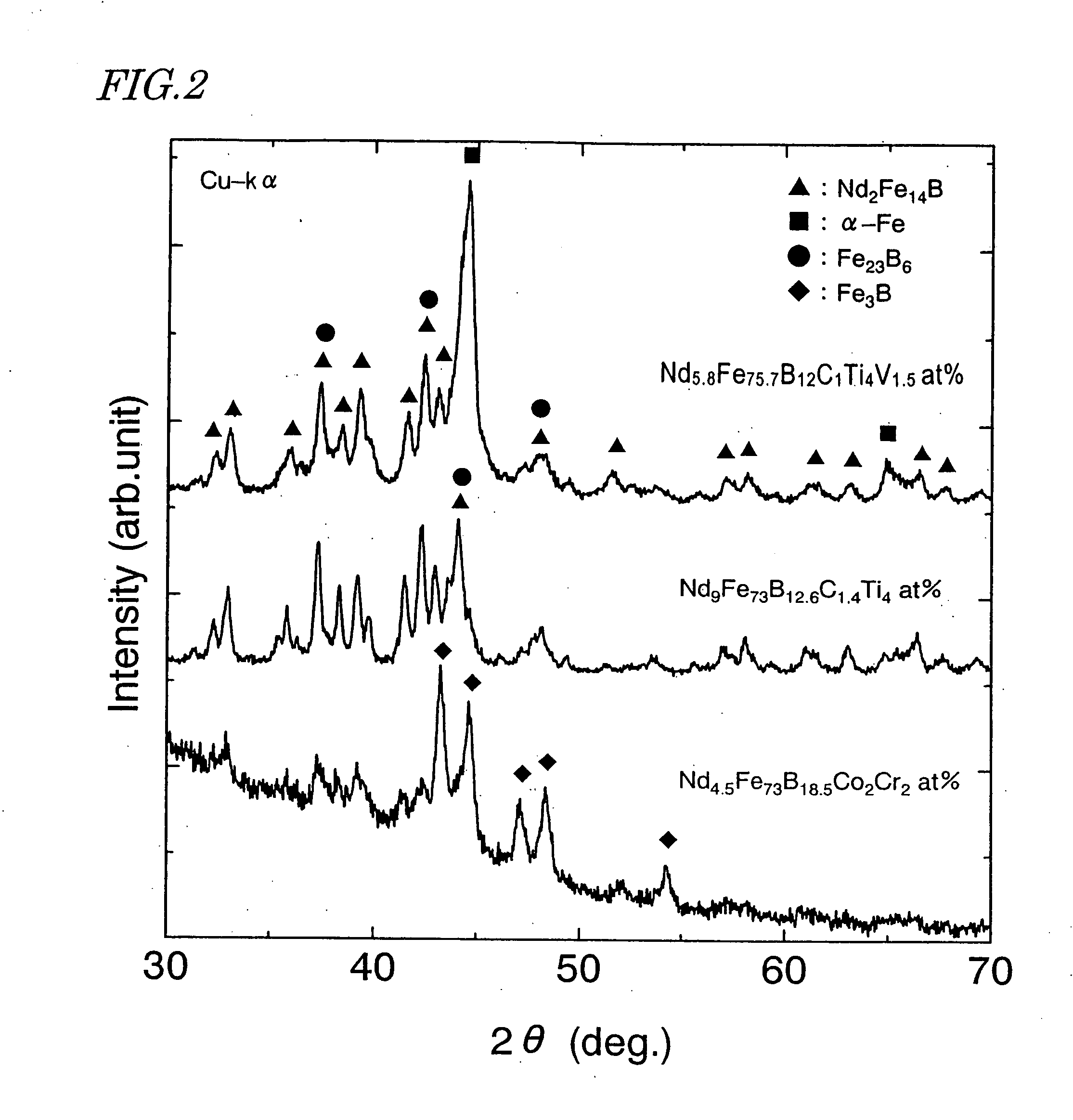
For each of the samples Nos. 1 to 8 shown in the following Table 1, the respective materials B, C, Fe, Co, Ti, V and Nd with purities of about 99.5% or more were weighed so that the sample had a total weight of about 600 g and then the mixture was put into a crucible of alumina. Thereafter, these alloyed materials were melted by an induction heating method within an argon (Ar) atmosphere at a pressure of about 70 kPa, thereby preparing a melt of the alloy. After the temperature of the melt had reached about 1,500° C., the melt was cast into a water-cooled copper mold to make a flat-plate alloy. Thereafter, the alloy was weighed so as to have a total weight of about 15 g and then put into a crucible of quartz having an orifice with a diameter of about 0.8 mm at the bottom. Then, the alloy was melted by an induction heating method within an argon (Ar) atmosphere at a pressure of about 1.33 kPa to about 47.92 kPa, thereby preparing a melt of the alloy. After the temperature of the mel...


PUM

PropertyMeasurementUnit
Fractionaaaaaaaaaa
Nanoscale particle sizeaaaaaaaaaa

Abstract

A nanocomposite magnet represented by the general formula: (Fe1-mTm)100-x-y-z-w-n(B1-pCp)xRyTizVwMn, where T is Co and/or Ni; R is a rare-earth element; M is at least one element selected from Al, Si, Cr, Mn, Cu, Zn, Ga, Nb, Zr, Mo, Ag, Ta and W; and x, y, z, w, n, m and p satisfy: 10 at %<x≦15 at %; 4 at %≦y<7 at %; 0.5 at %≦z≦8 at %; 0.01 at %≦w≦6 at %; 0 at %≦n≦10 at %; 0≦m≦0.5; and 0.01≦p≦0.5, respectively. The magnet includes a hard magnetic phase with an R2Fe14B type crystal structure and a soft magnetic phase. At least one of the coercivity and the maximum energy product of the nanocomposite magnet is at least 1% higher than that of a magnet including no V.

Description

TECHNICAL FIELD The present invention generally relates to a nanocomposite magnet that is applicable for use in motors and actuators of various types and a method for producing such a magnet. More particularly, the present invention relates to a nanocomposite magnet that includes a compound having an R2Fe14B-type crystal structure as a hard magnetic phase and α-Fe and other soft magnetic phases. BACKGROUND ART Recently, it has become more and more necessary to further improve the performance of, and further reduce the size and weight of, consumer electronic appliances, office automation appliances and various other types of electric equipment. For these purposes, a permanent magnet for use in each of these appliances is required to maximize its performance to weight ratio when operated as a magnetic circuit. For example, a permanent magnet with a remanence Br of 0.5 T or more is now in high demand. Hard ferrite magnets have been used widely because magnets of this type are relativ...

Claims


Application Information

Patent Timeline
IPC IPC(8): H01F1/053B82B3/00C22C38/00H01F1/057H01F1/08H01F41/02
CPCB82Y25/00H01F41/0266H01F1/0579H01F1/153H01F1/15325H01F1/15333
Inventor MIYOSHI, TOSHIOKANEKIYO, HIROKAZU
Owner SUMITOMO SPECIAL METAL CO LTD
Why Eureka
Try Eureka