Flow distributor device for an extruder

a distributor device and extruder technology, applied in cocoa, application, food preparation, etc., can solve the problems of inability to cope with the higher extrudate flow rate, inability to achieve the effect of increasing and reducing the cost of production, so as to achieve the effect of increasing the length and volume, substantially unidirectional laminar flow, and increasing the overall extrudate throughpu

Inactive Publication Date: 2005-03-03
MARS INC
View PDF7 Cites 7 Cited by
  • Summary
  • Abstract
  • Description
  • Claims
  • Application Information

AI Technical Summary

Benefits of technology

[0013] The significant advantage provided by the invention is that the increased length, and volume, of the passage between the extruder and cooling die allows the extrudate, which may be undergoing preliminary solidification, to maintain substantially unidirectional laminar flow. Therefore, the desirable structures that may be formed in the extrudate are not subjected to destructive turbulent flow, which would necessitate operating the extruder at inefficiently high temperatures, as outlined in the discussion on the prior art.
[0014] For example, for a given extrudate formulation, where a prior art system has been employed, the cooling die may be required to reduce extrudate temperature from 160° C. to less than 100° C., a reduction of greater than 60° C. However, utilising the invention, via for example a flow distribution device, fitted between an extruder and a multi-channel cooling die, the extrudate temperature at the extruder outlet may be run at 120° C. Therefore the cooling die is only then required to reduce the extrudate temperature by about 20° C. This effectively allows an increase in overall extrudate throughput of 200%, and will assist in reducing the incidence of product burning.
[0015] Preferably, the internal profile of the passage is substantially ovoid in cross-section. Even more preferably, the passage features an intermediate throat, wherein the maximum internal dimension at said throat is not greater than the minimum dimension of the extruder outlet. The particular advantage afforded by the throat feature is that it ensures that the flow path length, of any element of extrudate, from said throat to the entry point of any given extrudate channel in the cooling die is substantially the same. This in turn promotes very even, non-turbulent flow.
[0016] A particularly advantageous embodiment is provided where said passage is defined by the internal profile of a hollow connecting piece, said connecting piece in

Problems solved by technology

Of course, a limitation to the commercial usage of cooling dies in high moisture extrusion applications has been that such cooling dies tend not to be able to cope with the higher extrudate flow rates that are required when making a commercially viable food product, for example in excess of 200 kg of product per hour per extrusion unit.
However, one potential problem arises with multi-channel cooling dies where a single product stream exiting the extruder is split into a multitude of individual flow streams upon entry into the cooling die.
However, a drawback with such a system is that extrudate material of the kind required for the production of some commercial pet food products will

Method used


Image

  • Flow distributor device for an extruder
  • Flow distributor device for an extruder
  • Flow distributor device for an extruder

Examples


Embodiment Construction

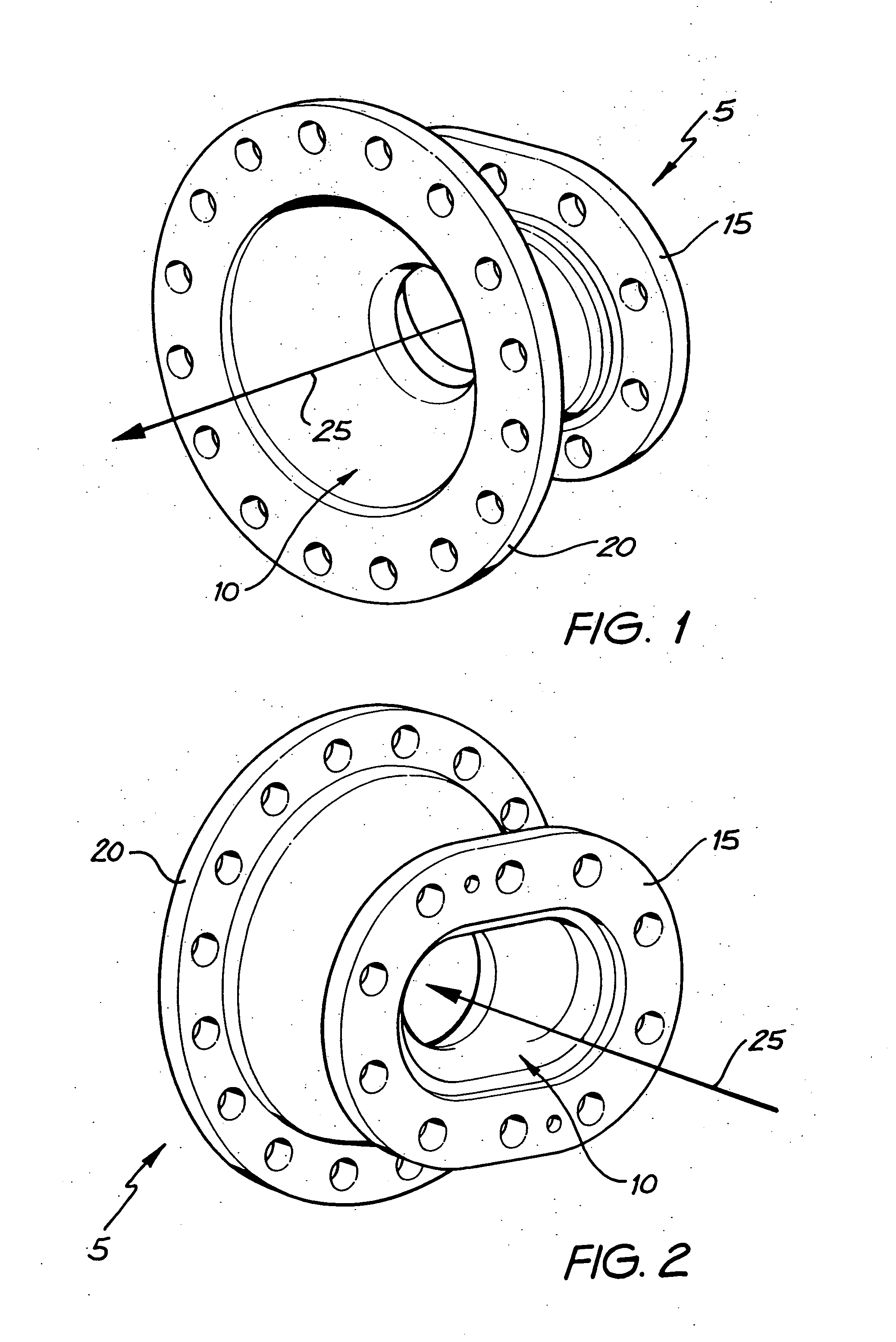
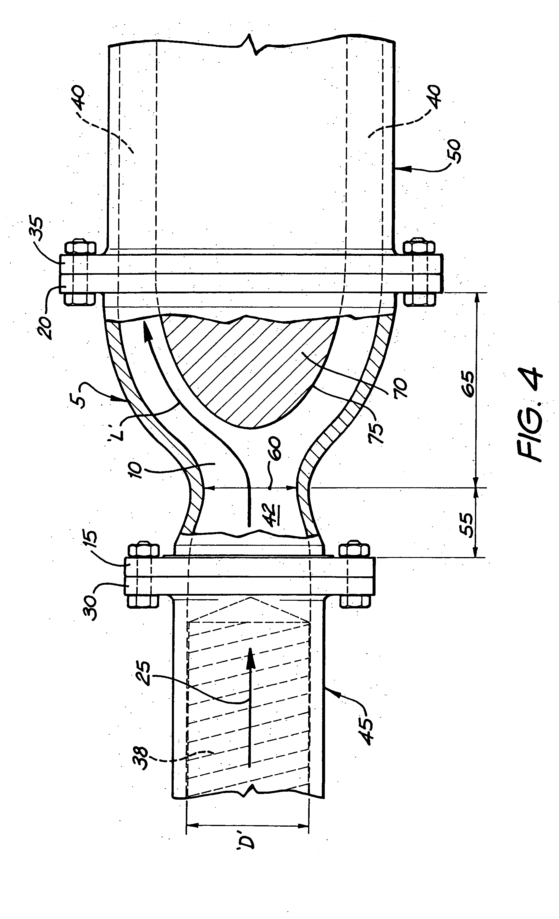
[0025] Turning first to FIG. 1, there is depicted a flow distribution device 5, consisting of an extrudate passage 10, defined by an internal surface of curvilinear profile, an extruder-connection flange 15 and a cooling die connection flange 20. It will be noted that, when in operation, extrudate 42 will enter the device 5 via the extruder connection flange 15, travel through the device 5 in the direction of the arrow 25 and will exit the device 5 and pass into the cooling die 50 via the cooling die connection flange 20. Turning to FIG. 2, the same features are shown from the opposite end of the device 5.

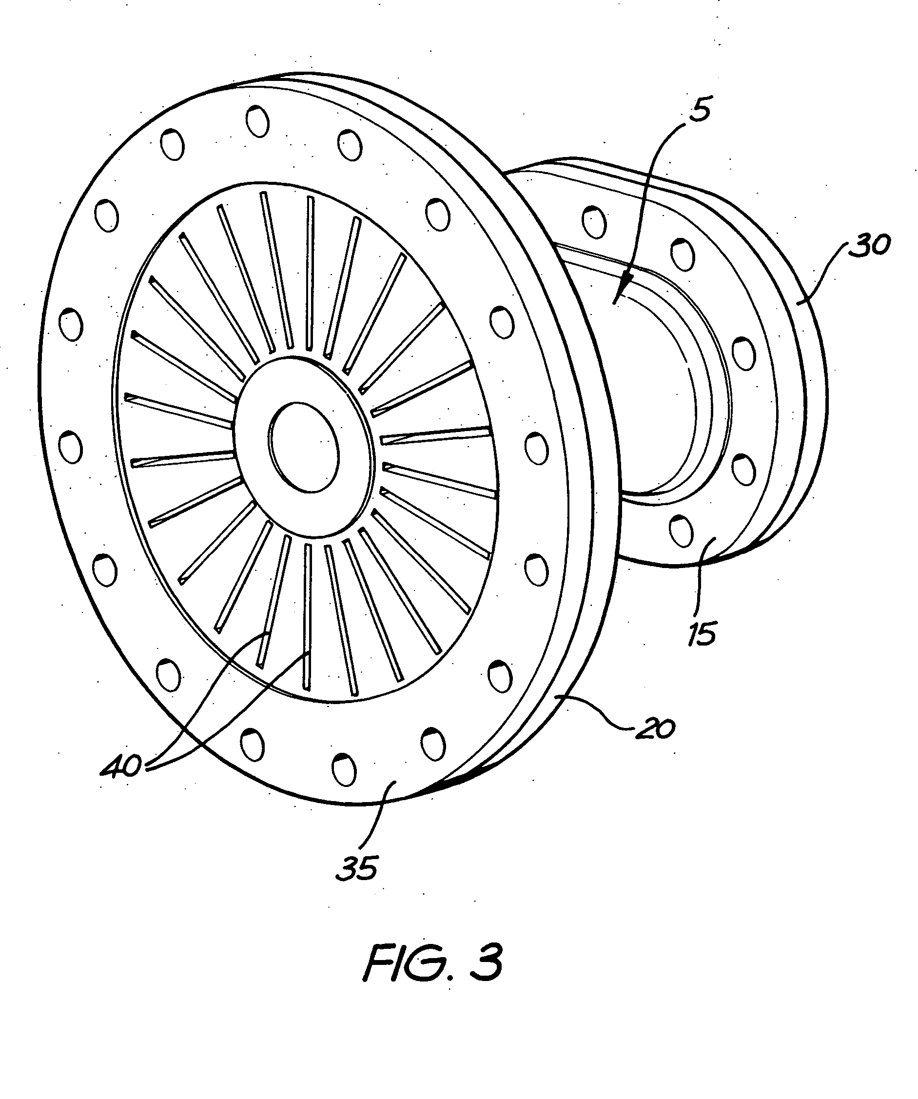
[0026] The flow distribution device 5, in practical operation, is directly connected to the outlet of a twin-screw conveying food extruder 45, for example of the type marketed by Buler AG, of 9240 Uzwil, Switzerland, via said extruder's outlet flange 30. It is similarly connected to a multi-channel cooling die 50, whose extrudate flow channels 40 are arranged radially about a circ...


PUM

PropertyMeasurementUnit
Flow rateaaaaaaaaaa
Diameteraaaaaaaaaa
Lengthaaaaaaaaaa

Abstract

An extruder exit flow distribution device, for use in the transfer of high-moisture food extrudate material from an extruder, said extruder having one or more extrusion screws, to the inlet of a multi-channel cooling die, said flow distribution device having an internal extrudate passage which defines a flow path for any given element of extrudate passing from the extruder exit to the entrance of said cooling die.

Description

CROSS-REFERENCE TO RELATED APPLICATIONS [0001] This application claims priority to Australian Application No. 2003904709 filed Aug. 29, 2003. TECHNICAL FIELD [0002] This invention relates to cooling dies and their use in association with food extruders in the manufacture of texturised protein food products, and to a flow distribution device which may be used to direct flow from the outlet of a food extruder to the inlet of a multi-channel cooling die. In particular, this invention relates to a device which is designed to improve the efficiency of operation of the cooling die and which also acts to promote an even distribution of extrudate flow in each of the channels of the cooling die. BACKGROUND OF THE INVENTION [0003] In the field of commercial food manufacture, in particular in the field of commercial pet food manufacture, it is often desired to produce a low-cost meat analogue for inclusion in a food matrix, in order to ensure that the food has an authentic “meaty” appearance, ...

Claims


Application Information

Patent Timeline
IPC IPC(8): A23P1/12B29C48/03B29C48/30B29C48/87B29K77/00
CPCA23P1/12B29C47/8835B29C47/0009A23P30/20B29C48/03B29C48/87B29C48/913A23J3/26
Inventor ALEXANDER, DAVIDREES, KEVIN
Owner MARS INC
Why Eureka
Try Eureka