
Method and apparatus for fractional photo therapy of skin

Inactive Publication Date: 2005-03-03
RELIANT TECH INC
View PDF99 Cites 454 Cited by
  • Summary
  • Abstract
  • Description
  • Claims
  • Application Information

AI Technical Summary

Benefits of technology

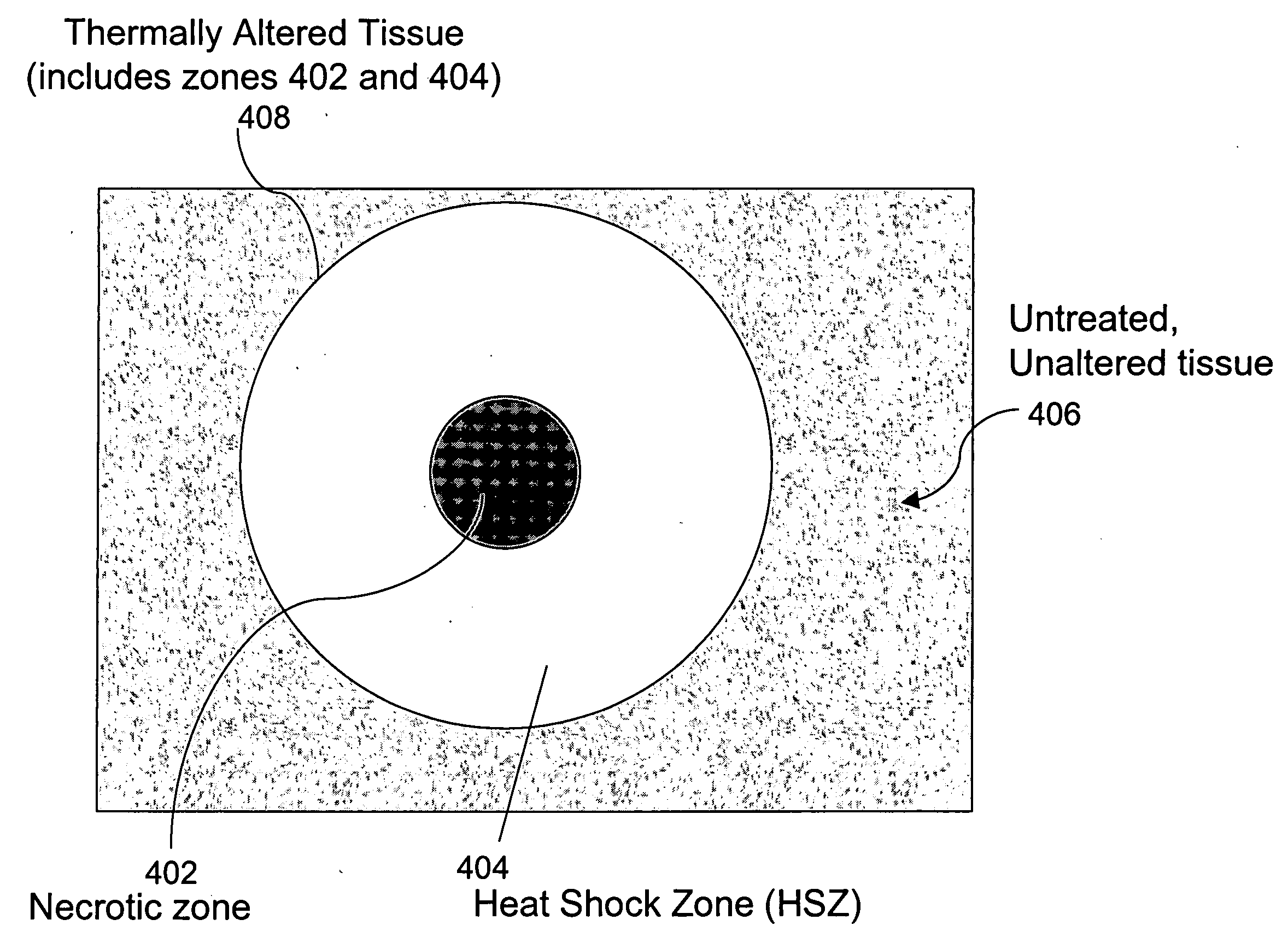
In general, the present invention features a method for treating either existing medical (e.g., dermatological) disease conditions or for improving the appearance of tissue (e.g., skin) by intentionally generating a pattern of thermally altered tissue surrounded by unaltered tissue. The thermally altered tissue may include a necrotic zone. This approach offers numerous advantages over existing approaches in terms of safety and efficacy. This invention minimizes the undesirable side effects of pain, erythema, swelling, fluid loss, prolonged reepithelialization, infection, and blistering generally associated with laser skin resurfacing. Another aspect of this invention is to stimulate the tissue's wound repair system, by sparing healthy tissue around the thermally altered tissue, whereby the repair process is more robust. Yet another distinguishing feature of this invention is to reduce or eliminate the side effects of repeated laser treatment to tissue by controlling the extent of tissue necrosis due to laser exposure.
One aspect of the present invention is a method for achieving beneficial effects in a target biological tissue comprising treating the target tissue using optical radiation to create one or more “microscopic” treatment zones such that the aspect ratio of the necrotic zone width to the necrotic zone depth is above about 1:2, preferably above about 1:4, and the treatment zones are created by a predetermined treatment pattern. Another aspect of this invention is a method for achieving beneficial effects in skin tissue comprising treating the skin by exposing a targeted part of the skin tissue to optical radiation to create one or more microscopic treatment zones such that the volume of the target tissue that remains unaffected by the optical radiation is controlled, and further that the ratio of the sum of the treatment zone volumes to the target tissue volume is less than one.
Another specific aspect of this invention is a method of creating the microscopic treatment zones of necrosed tissue that allows viable tissue to be interspersed between the microscopic treatment zones thereby enabling the skin to mount a more robust repair response.

Problems solved by technology

It has been widely reported that such broad area treatment results in undesirable side effects such as intolerable pain, prolonged erythema, swelling, occasional scarring, extended healing times and infection.
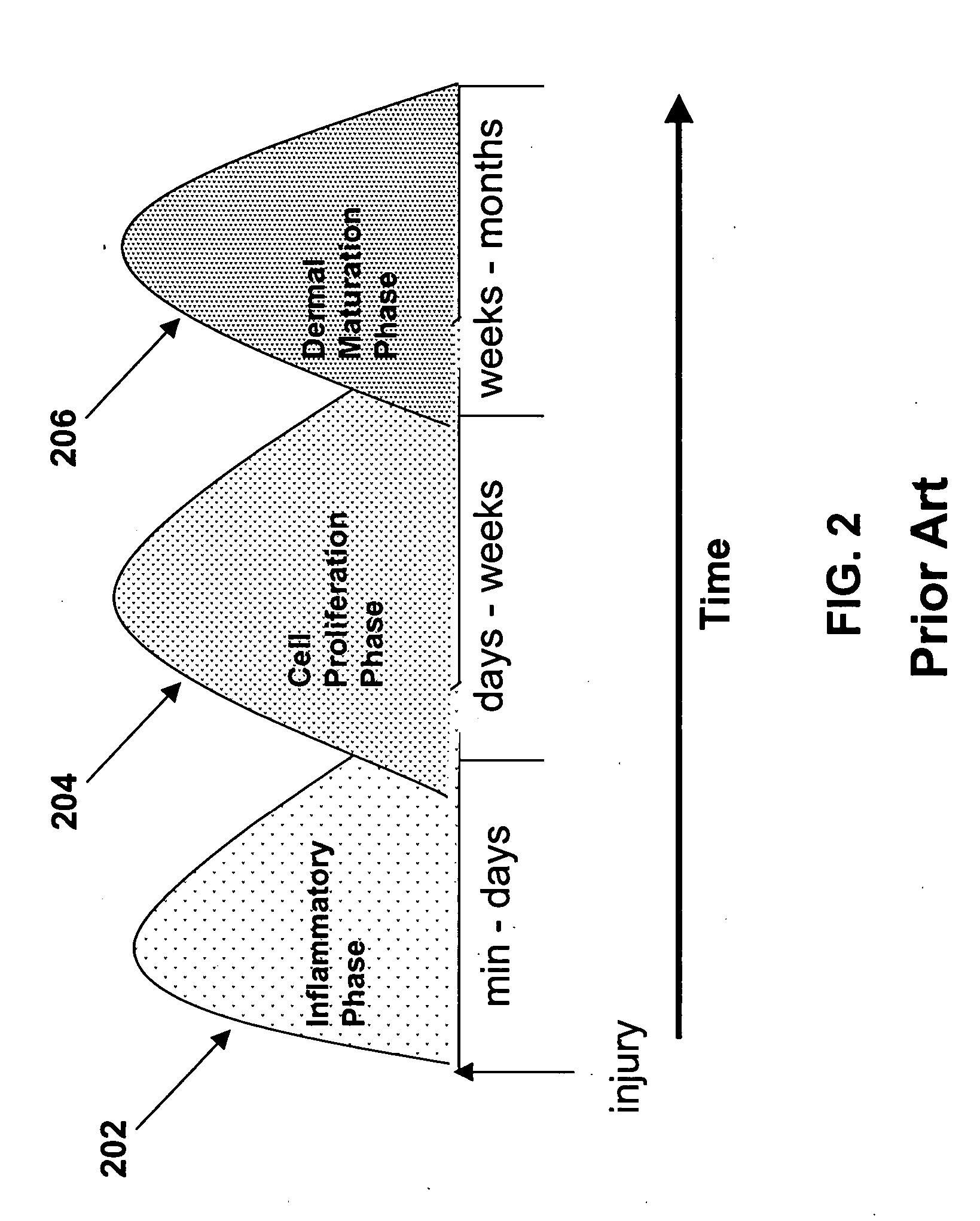
Prolonging and / or accentuating the inflammatory phase may be undesirable from a clinical perspective due to increased pain and extended wound repair, and may retard subsequent phases of wound repair.
Unfortunately, most of the skin resurfacing efforts and selective photothermolysis treatments that affect large contiguous areas of chromophores result in a prolonged, exaggerated inflammatory phase 202 leading to undesirable consequences such as delayed wound repair.
The prolonged inflammatory phase also leads to the pain experienced by most patients undergoing skin resurfacing procedures.
All of these systems pose practical limitations because of the complexity added by the cooling system.
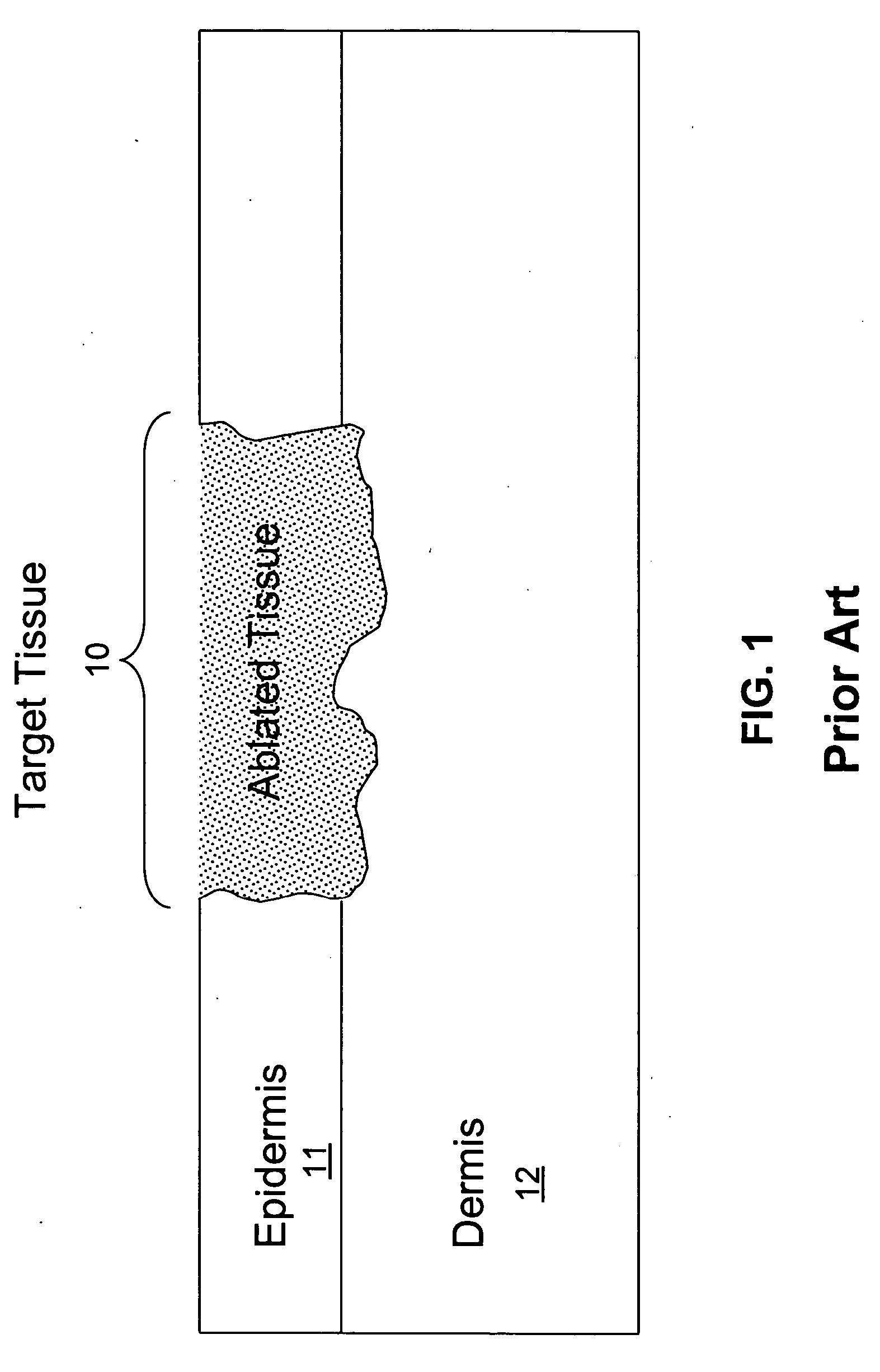
These global treatments lead to an increase in clinical side effects and to an increase in healing time as described above.
Temperatures in the tissue above about 100° C. may cause steam to form in the tissue, which may cause disruptive effects.

Method used


Image

  • Method and apparatus for fractional photo therapy of skin
  • Method and apparatus for fractional photo therapy of skin
  • Method and apparatus for fractional photo therapy of skin

Examples


embodiments and examples

One embodiment of the apparatus used for practicing this invention is shown in FIG. 15. Apparatus 1500 comprises a control system 1530, an optical radiation source 1510, and a delivery system 1520 to deliver the desired pre-determined treatment pattern to the target tissue 10. The control system 1530 is operably connected to the optical radiation source 1510 and the delivery system 1520. The control system 1530 may include separate control systems (not shown) for the optical system and the delivery system. For certain applications, the optical radiation source 1510 includes multiple laser light sources, which can be arranged in an array, such as a one-dimensional array or a two-dimensional array.

FIG. 16 shows a block diagram of the control system 1530. Control system 1530 is operably connected to the input / output 1602, the optical source 1604, the scanning element 1606, the optical element 1608 and the sensing element 1610. Input / Output 1602 could be a touch screen element or othe...


PUM


Abstract

A method and apparatus for providing fractional treatment of tissue (e.g., skin) using lasers is disclosed. The method involves creating one or more microscopic treatment zones of necrotic tissue and thermally-altered tissue and intentionally leaving viable tissue to surround the microscopic treatment zones. The dermatological apparatus includes one or more light sources and a delivery system to generate the microscopic treatment zones in a predetermined pattern. The microscopic treatment zones may be confined to the epidermis, dermis or span the epidermal-dermal junction, and further the stratum corneum above the microscopic treatment zones may be spared.

Description

FIELD OF THE INVENTION The present invention relates generally to methods and apparatus for providing medical or surgical treatment using optical energy, and in particular to a method and apparatus for providing fractional treatment of tissue (e.g., skin) using optical radiation. BACKGROUND OF THE INVENTION Optical energy, particularly laser energy, is commonly used as a versatile tool in medicine to achieve desired outcomes in the tissue that is treated. For example, lasers have been used to treat common dermatological problems such as hypervascular lesions, pigmented lesions, acne scars, rosacea, hair removal, etc. Additionally, lasers are also used in aesthetic surgery for achieving better cosmetic appearance by resurfacing the skin and remodeling the different layers of skin to improve the appearance of wrinkled or aged skin. Generally, skin resurfacing is understood to be the process by which the top layers of the skin are completely removed by using chemicals, mechanical abr...

Claims


Application Information

Patent Timeline
IPC IPC(8): A61B5/00A61B17/00A61B18/20
CPCA61B18/20A61B18/203A61B2017/00057A61B2018/2085A61B2018/0047A61B2018/2075A61B2018/208A61B2018/00452A61B2018/20351A61B2018/205545A61B2018/20359
Inventor DEBENEDICTIS, LEONARD C.HERRON, G. SCOTTSINK, ROBERT KEHLEIMERL, DAVIDLEMBERG, VLADIMIRVOEVODKIN, GEORGEBLACK, MICHAEL
Owner RELIANT TECH INC
Learn More