Switching power supply

a technology of switching power supply and power supply device, which is applied in the direction of electric variable regulation, process and machine control, instruments, etc., can solve the problems of difficult to reduce the size of the switching power supply device, and achieve the effect of high efficiency

Inactive Publication Date: 2005-03-10
PANASONIC CORP
View PDF5 Cites 46 Cited by
  • Summary
  • Abstract
  • Description
  • Claims
  • Application Information

AI Technical Summary

Benefits of technology

[0009] The present invention has been accomplished to solve the problems as described above, and its object is to provide a high efficiency and small-sized switching power supply device that is capable of supplying a direct current at low voltage and high current and at a constant voltage irrespective of the power consumption of load.

Problems solved by technology

That is, the configuration of the conventional switching power supply device 1000 has a problem that it is very difficult to reduce the size of a switching power supply device that is highly efficient and capable of outputting a direct current at low voltage and high current.

Method used


Image

  • Switching power supply
  • Switching power supply
  • Switching power supply

Examples


Embodiment Construction

[0055] Hereinbelow, preferred embodiments of the present invention are detailed with reference to the drawings.

[0056] First Preferred Embodiment

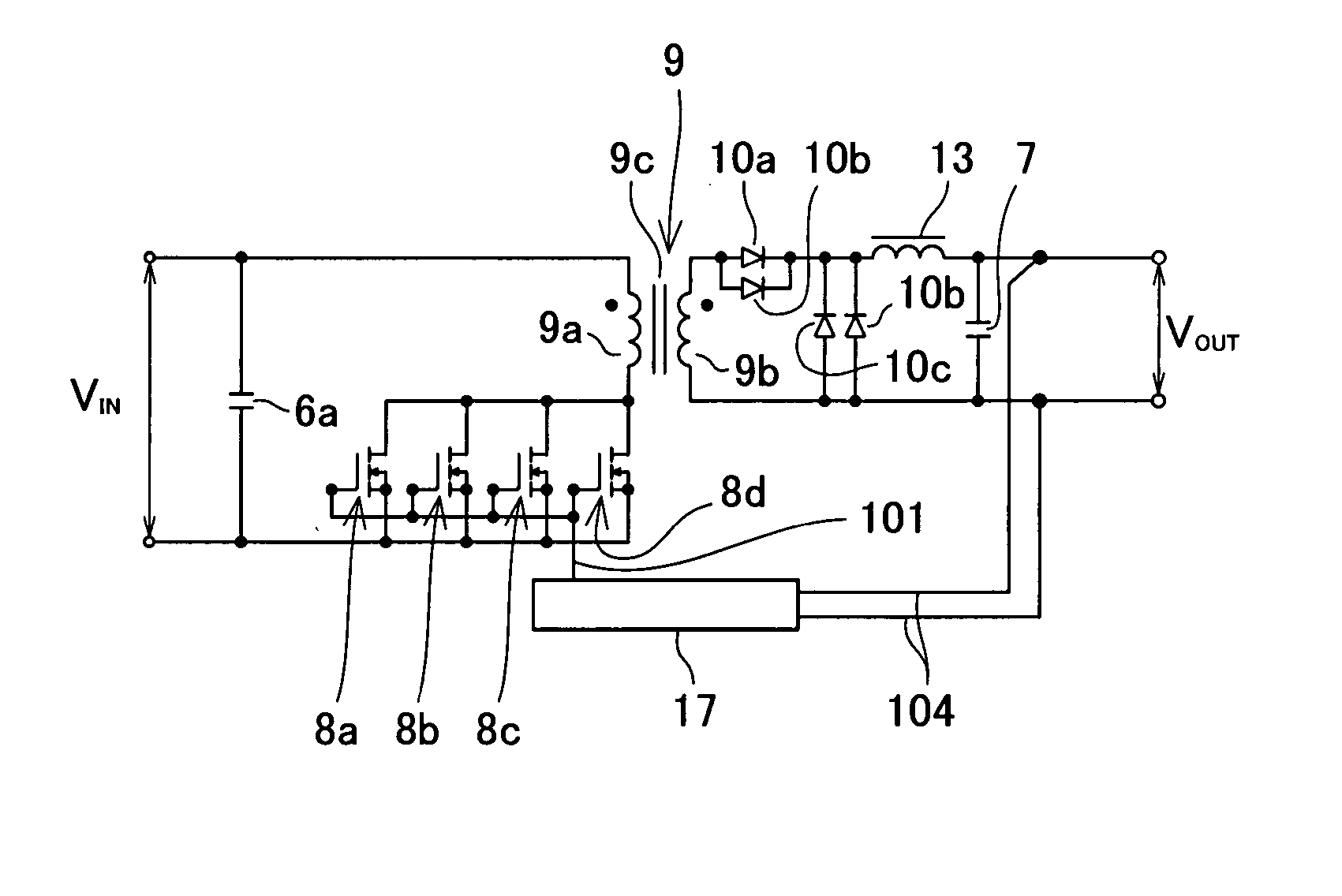
[0057]FIG. 4 is a circuit diagram of a switching power supply device 100 according to a first preferred embodiment of the present invention. As shown in FIG. 4, the switching power supply device 100 described in the present embodiment comprises: input smoothing capacitors 6a and 6b; n-channel type MOS field-effect transistors (hereafter abbreviated as “MOSFETs”) 8a and 8b; a transformer 9 including a transformer primary winding 9a, a transformer secondary winding 9b, and a transformer core 9c (the turns ratio being N:1); first and second diodes 10a and 10b; an inductance 13; an output smoothing capacitor 7; and a control circuit 17. These active elements and passive elements are electrically connected to form a predetermined circuit, and thus the switching power supply device 100 is configured.

[0058] The circuit diagram of the switching p...


PUM


Abstract

A switching power supply device of the invention includes: a switching circuit for interrupting direct current to generate a pulse voltage; a transformer including a primary winding, a secondary winding, and a core for magnetically coupling the primary winding and the secondary winding; a multi-layer wiring board having wiring lines constituting the primary winding and the secondary winding; a rectifier circuit for rectifying an alternating current; a smoothing circuit for suppressing ripple; and a control circuit for controlling an output voltage from the smoothing circuit. The multi-layer wiring board is provided with at least the switching circuit and the rectifier circuit and is arranged on a main wiring board, and the control circuit is arranged on the main wiring board.

Description

BACKGROUND OF THE INVENTION [0001] 1. Field of the Invention [0002] The present invention relates to a switching power supply device installed in the interior of electronic equipment. [0003] 2. Description of the Related Art [0004] Conventionally, power supply devices that are incorporated in electronic equipment, such as personal computers, use a switching power supply device. The switching power supply device is one type of stabilized (regulated) direct current power supply, and is configured so as to output a direct current at a constant voltage by converting a direct current obtained from a power supply, such as a commercial power source or a storage battery, into a pulse voltage having a frequency higher than the audio frequency (about several hundred kilohertz) by a high-speed switching function of semiconductor devices such as transistors, and controlling the pulse width and the pulse interval of the pulse voltage. The switching power supply device thus configured has such fe...

Claims


Application Information

Patent Timeline
Patent Type & Authority Applications(United States)
IPC IPC(8): H02M7/00H05K1/00H05K1/14H05K1/16H05K3/20
CPCH02M7/003H05K1/0298H05K1/141H05K2201/09063H05K1/165H05K3/202H05K2201/086H05K1/144
Inventor TAKESHIMA, YOSHIHIROYOSHIDA, KOJIIKEDA, SATOSHIMATSUO, MITSUHIRO
Owner PANASONIC CORP
Why Eureka
Try Eureka