
Endoscope

a technology of endoscope and endoscope, which is applied in the field of endoscope, can solve the problems of rust generation, deterioration of operability at the time of inserting endoscope, and deterioration of operability at the time of endoscope inserting,

Inactive Publication Date: 2005-03-17
OLYMPUS CORP
View PDF9 Cites 18 Cited by
  • Summary
  • Abstract
  • Description
  • Claims
  • Application Information

AI Technical Summary

Benefits of technology

[0015] A main object of the present invention is to provide an endoscope which is capable of overcoming the aforementioned problems and is free from the aforementioned problems even if the endoscope is subjected to autoclave sterilization (high-pressure / high-temperature steam sterilization).

Problems solved by technology

However, since the stainless steel strip and the phosphor bronze strip are relatively large in specific gravity and hence relatively heavy, an intermediate portion of the flexible tube, e.g. an intermediate portion located between the proximal portion of the flexible tube and the distal end portion of the flexible tube which is inserted into a living body, is caused to sag down during the operation of the endoscope, generating those portions of the flexible tube which are not straight line or arc, thus raising the problem that the operability at the time of inserting the endoscope is deteriorated.
Further, since the stainless steel wire to be employed as a raw material for the net tube is also relatively large in specific gravity and hence relatively heavy, there is also a problem that the operability at the time of inserting the endoscope is deteriorated.
However, the employment of such an autoclave sterilization is accompanied with various problems associated with the aforementioned flexible tube, optical fiber bundle and the channel tube.
Namely, when the net tube to be used for the flexible tube is formed by knitting a common stainless steel wire, water vapor used during the autoclave sterilization (high-pressure / high-temperature steam sterilization) can enter and remain in the interstices of the net-like wire structure, thereby giving rise to the generation of rust and hence the generation of discontinuity of the wire in the net-like wire structure (see for example, JP Laid-open Patent Publication (Kokai) No. 2001-46330).
Further, when a net tube made of carbon fiber is employed, the carbon fiber may be caused to break on the occasion of knitting the carbon fiber, and therefore, there are many reasons why it may become difficult to form a net tube having a sufficient mechanical strength.
As a result, the opposite ends of the optical fiber bundle are caused to become free of the protective tube and hence caused to break, thereby possibly giving rise to the problem that it may become impossible to obtain satisfactory illumination and images.
Likewise, the silk or nylon thread that has been wound around the outer peripheral surface of the channel tube for securing the channel tube to the channel pipe is caused to become free of the outer peripheral surface of the channel tube due to the hydrolysis of the fibrous polymer by the effects of the water vapor used in an autoclave sterilization, thereby possibly giving rise to the problem that it may become impossible to obtain the predetermined performance of the channel tube.

Method used


Image

  • Endoscope
  • Endoscope

Examples


example 1

[0051] This example illustrates one embodiment where the present invention was applied to the flexible tube of the endoscope.

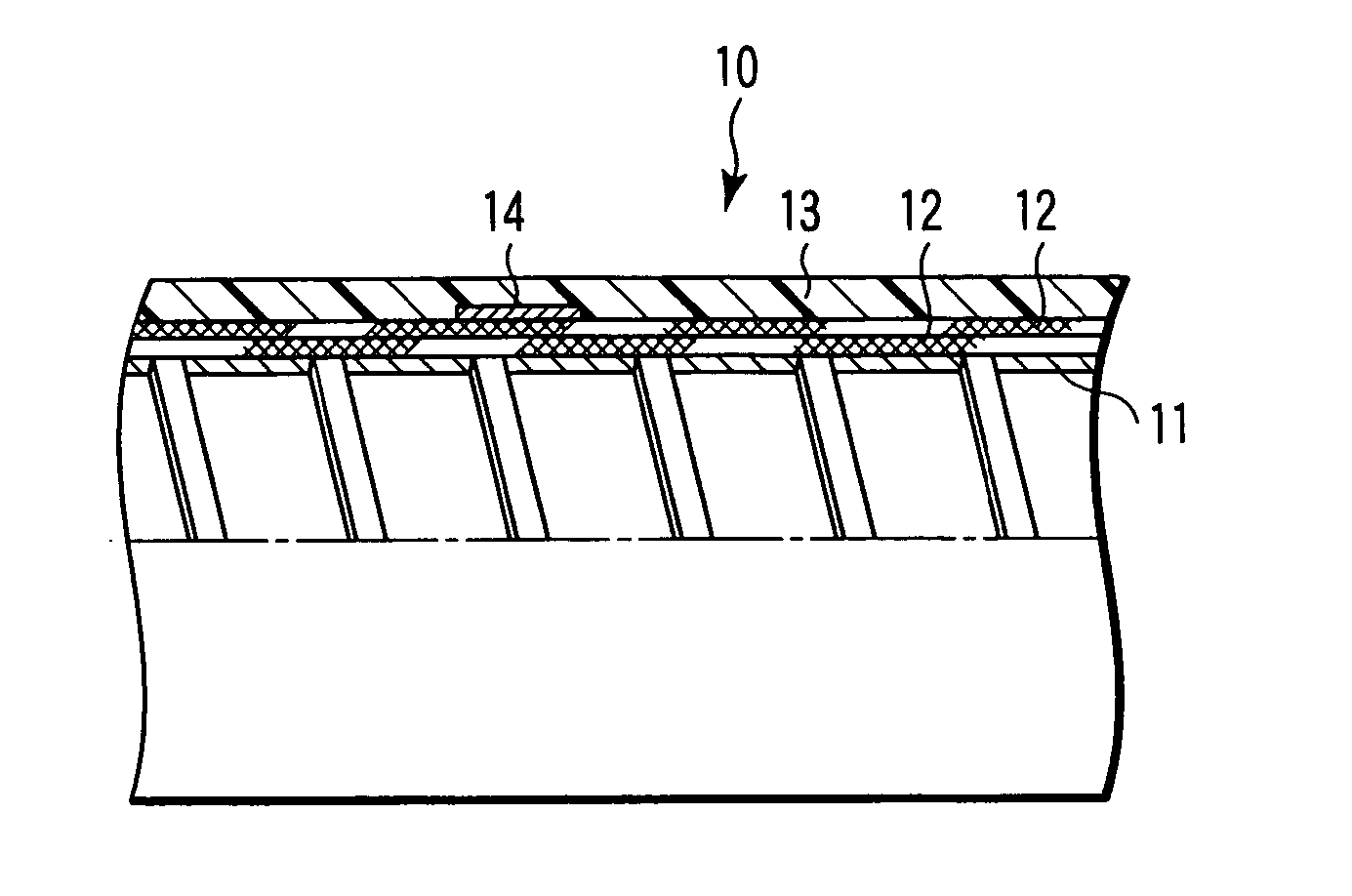
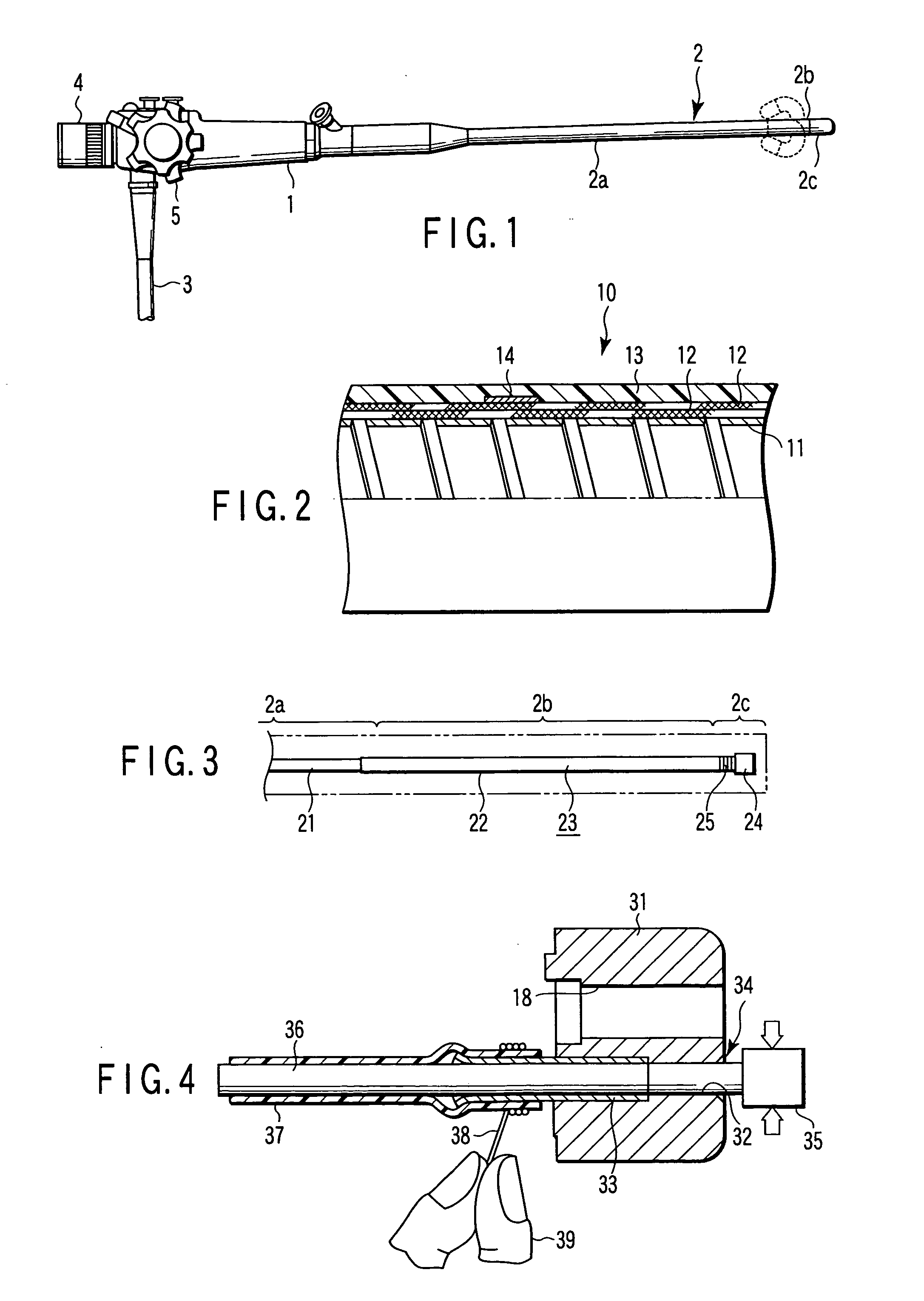
[0052]FIG. 2 shows the flexible tube constituting an insertion part 2, wherein the optical fiber bundle, etc. which is inserted therein is omitted. The innermost layer of the flexible tube 10 is constituted of a helical tube 11 formed by helically winding a strip member so as to provide a tubular structure having a fixed diameter. The outer peripheral surface of the helical tube 11 is covered by a 2-ply layer of a net tube (braid) 12 which is formed by knitting yarn to tubular structure.

[0053] The outer peripheral surface of the net tube 12 is covered by an outer skin member 13 formed of a polyester tube. Alternatively, this outer skin member 13 may be formed by way of extrusion molding, dipping, etc. Incidentally, reference numeral 14 denotes a fluoroscopic indicator consisting of an X-ray. impermeable member such as a thin lead plate for example.

[0054] In...

example 2

[0056] This example illustrates one embodiment where the present invention was applied to the fixing of the optical fiber bundle housed in the insertion part of endoscope.

[0057] The light guide and image guide housed inside the insertion part 2 shown in FIG. 2 are formed of an optical fiber bundle comprising a large number of fine optical fibers which are bundled en bloc. Since individual optical fiber constituting the optical fiber bundle is very fragile, the optical fiber bundle is inserted in a protective member in order to protect each of these optical fibers, thus forming, for example, an image guide assembly as a whole.

[0058]FIG. 3 shows an overall external view of one example of this image guide assembly. In FIG. 3, the optical fiber bundle 21 is inserted into and covered by a thin wall protective tube 22, thus forming an image guide main body 23. The distal end portion of the image guide main body 23 is fixed by way of the engagement of thin wall protective tube 22 with a ...

example 3

[0061] This example illustrates one embodiment where the present invention was applied to the fixing of the channels housed in the insertion part of endoscope.

[0062]FIG. 4 is a cross-sectional view illustrating a secured portion formed between a channel pipe and a channel tube.

[0063] In FIG. 4, the connection between the channel pipe and the channel tube can be performed as follows.

[0064] First of all, a channel pipe 33 is inserted into the passageway 32 of the distal main body 31 of the insertion part 2. Then, a core bar 34 is inserted into the passageway 32 and into the channel pipe 33. This core bar. 34 is constituted of a grip portion 35 and a cylindrical portion 36. Thereafter, a channel tube 37 covers on the outer peripheral surface of the cylindrical portion 36 of the core bar 34 which is protruded from the interior of the channel pipe 33. In this case, the proximal end portion of the channel tube 37 covers on the channel pipe 33.

[0065] Then, by way of manipulation by han...


PUM


Abstract

An endoscope comprising an operation part, and an intracavital insertion part attached to the operation part and formed of a flexible tube, wherein the yarn employed for the component member of the flexible tube and the yarn employed for fixing the internal member contained in the flexible tube respectively contain aramid fiber.

Description

CROSS-REFERENCE TO RELATED APPLICATIONS [0001] This application is based upon and claims the benefit of priority from prior Japanese Patent Application No. 2003-311470, filed Sep. 3, 2003, the entire contents of which are incorporated herein by reference. BACKGROUND OF THE INVENTION [0002] 1. Field of the Invention [0003] The present invention relates to an endoscope, and in particular, to an endoscope which is improved in a flexible tube constituting an insertion part thereof, in the fixing of an optical fiber bundle assembly which is contained in the insertion part, and in the fixing of channels. [0004] 2. Description of the Related Art [0005] The insertion part of an endoscope which is adapted to be introduced into a body cavity is constituted of a flexible tube 10 in which an optical fiber bundle, such as an image guide and various kinds of channels, are accommodated. [0006] This flexible tube constituting the insertion part of the endoscope is generally constructed such that it...

Claims


Application Information

Patent Timeline
Patent Type & Authority Applications(United States)
IPC IPC(8): G02B23/24A61B1/00A61B1/005
CPCA61B1/00071A61B5/064A61B1/0055A61B1/0011
Inventor MATSUMOTO, JUNNIHEI, TOSHIYUKIKAGAWA, ICHIRO
Owner OLYMPUS CORP
Learn More