Information recording medium and its control method and information recording/reproducing method

a technology of information recording medium and control method, which is applied in the direction of optical recording/reproducing/erasing method, recording signal processing, instruments, etc., can solve the problems of unfavorable disk damage, difficult or impossible to increase the recording speed, and the recording speed of the optical disk is to be further increased, so as to achieve the effect of cheap manufactur

Inactive Publication Date: 2005-03-24
HITACHI LTD
View PDF12 Cites 16 Cited by
  • Summary
  • Abstract
  • Description
  • Claims
  • Application Information

AI Technical Summary

Benefits of technology

In the light of the state of the art described above, it is an object of the present invention to provide a high-

Problems solved by technology

However, with the conventional control data recording method or scheme, there arises a problem when the recording speed of the optical disk is to be further increased, that is, the linear velocity becomes extremely high in the radially inner zone of the disk, making it practically difficult or impossible to increase the recording speed.
At such a high speed rotation, vibration will occur in the disk drive apparatus under the influence of the centrifugal force, being accompanied with

Method used


Image

  • Information recording medium and its control method and information recording/reproducing method
  • Information recording medium and its control method and information recording/reproducing method
  • Information recording medium and its control method and information recording/reproducing method

Examples


embodiment 1

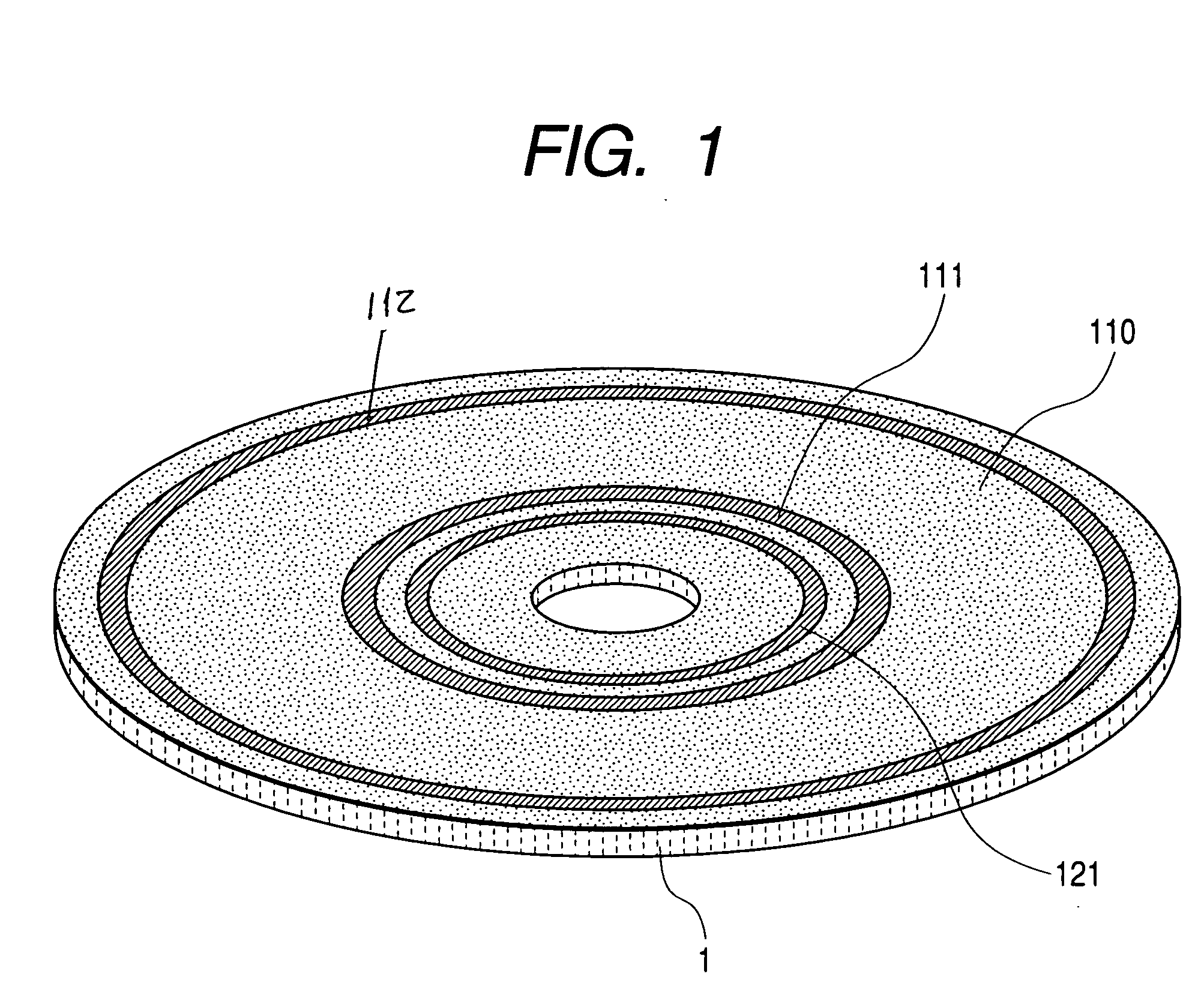
FIG. 1 is a view showing schematically an arrangement or disposition of recording zones on a recording medium 1 according to a first embodiment of the present invention. Referring to the figure, maximum linear velocities and minimum linear velocities for a radially innermost zone 111 and a radially outermost zone 112, respectively, which belong to a user data area 110 on a disk-like recording medium are recorded in a control data zone 121 which is located at a lead-in portion at the radially inner side of the user data area 110. Some of the recorded contents of the control data are shown in FIG. 8. More specifically, FIG. 8 shows extractively a portion of the control data zone 121 where information concerning the linear velocities mentioned above are set forth or recorded.

Referring to FIG. 8, in a column labeled “RBP”, there are entered relative byte positions (RBPs), wherein each entry is represented by one byte, i.e., eight bits. At the locations where RBP=0, RBP=1 and RBP=2, th...

embodiment 2

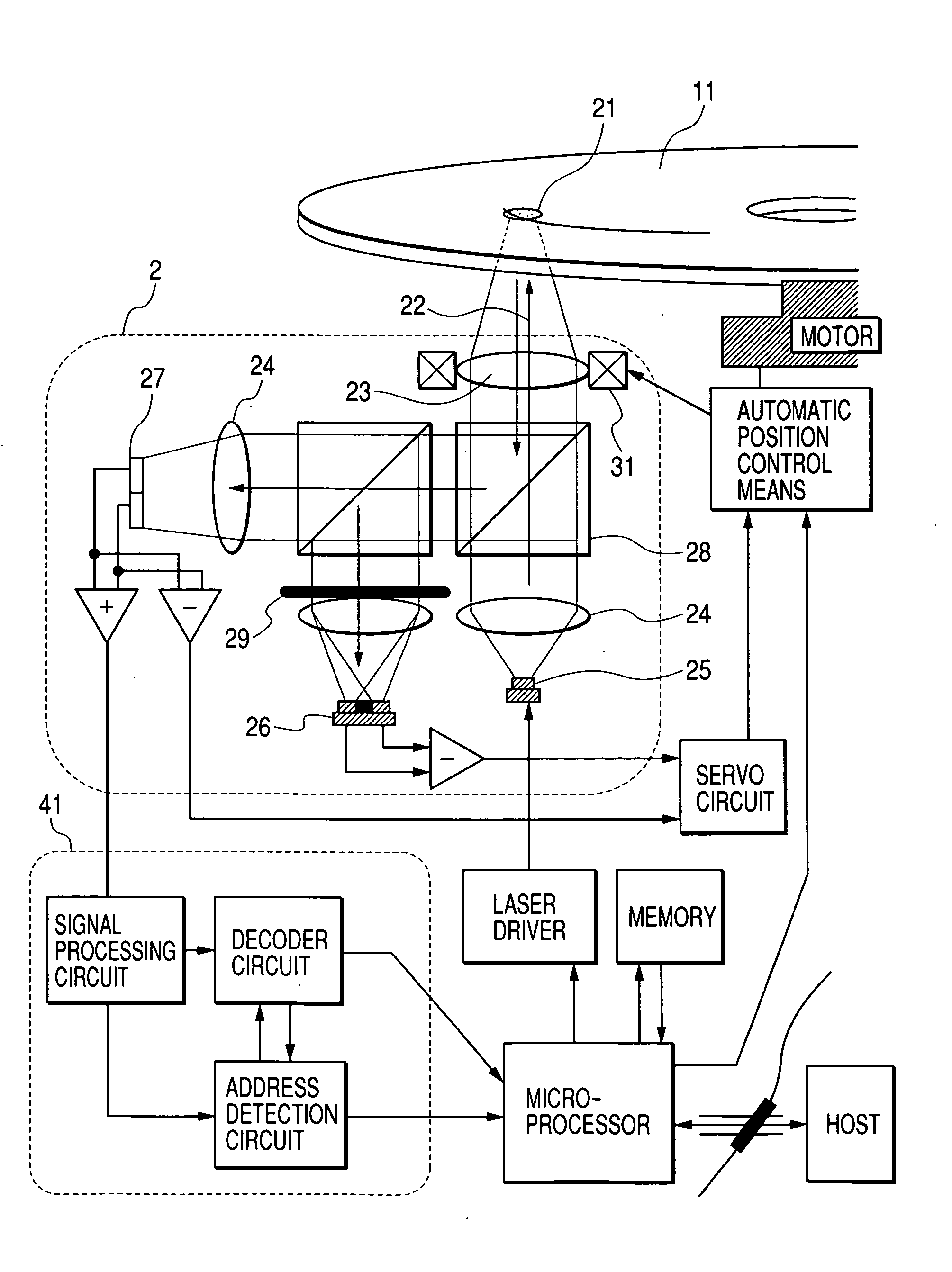
An example of the optical recording apparatus according to an embodiment of the present invention will be described by reference to FIG. 14.

FIG. 14 is a block diagram showing schematically a configuration of the optical recording apparatus according to an embodiment of the present invention. Referring to FIG. 14, light emanated from a laser source 25 implemented as a part of an optical head 2 and having a wavelength of about 405 nm is collimated to a substantially parallel optical beam 22 through a collimating lens 24. The optical beam 22 is projected onto an optical disk 11 through an objective lens 23 to form a spot 21 on the optical disk 11. Subsequently, the optical beam 22 reflected from the optical disk 11 is guided to a servo-dedicated detector 26 and a signal detector 27 through the recording medium of a beam splitter 28, a holographic element 29 and others. The signals outputted from the detectors undergo addition / subtraction processings to be transferred to a servo signa...

embodiment 3

FIG. 9 is a schematic cross-sectional view of the recording medium according to a third embodiment of the invention. The recording medium now of concern is a rewritable DVD medium designed for recording / reproducing with a laser beam having a wavelength of 650 nm at NA of 0.6. Referring to FIG. 9, the recording medium includes a subassembly composed of a substrate 131 on which a dielectric layer 132, a phase-change recording layer 133, a dielectric layer 134 and a metal reflective layer 135 are deposited in this order. The subassembly mentioned above is bonded to a dummy substrate 137 by a UV curing resin 136. At this juncture, it is to be mentioned that the thickness of the metal reflective layer 135 is gradually decreased in the direction from the radially innermost zone or location toward the radially outermost zone or location. FIG. 12 is a view for illustrating an example of the method of manufacturing the metal reflective layer 135 by changing the thickness thereof in the manne...


PUM


Abstract

An information recording medium includes data concerning a maximum linear velocity (V1max) and a minimum linear velocity (V1min) at a first location on the medium and a maximum linear velocity (V2max) and a minimum linear velocity (V2min) at a second location on the medium, are recorded at a predetermined location on said medium, and at the first and second locations both of which are located at different locations on the medium, performing selectively CLV/CAV (Constant Linear Velocity/Constant Angular Velocity) control or alternatively a CLV/CAV-hybrid control.

Description

CROSS-REFERENCE TO RELATED APPLICATION This application relates to and claims priority from Japanese Patent Application No. 2003-329295, filed on Sep. 22, 2003, the entire disclosure of which is incorporated herein by reference. BACKGROUND OF THE INVENTION 1. Field of the Invention The present invention generally relates to a high-speed information recording system for recording and / or reproducing information at a high speed by using an energy beam. More particularly, the present invention relates to an information recording medium different in a relative moving speed of the energy beam at locations on the recording medium, capable of removing the medium, and applicable to a removable type disk-like recording medium. The present invention also relates to a method of recording or reproducing information on or from the information recording medium. 2. Description of the Related Art First, description will be made of an exemplary or conventional optical recording apparatus by refe...

Claims


Application Information

Patent Timeline
IPC IPC(8): G11B7/00G11B7/004G11B7/0045G11B7/005G11B7/007G11B7/24062G11B7/24097G11B19/26G11B19/28
CPCG11B19/26G11B7/00736
Inventor MIYAMOTO, HARUKAZUNISHIMURA, KOICHIRO
Owner HITACHI LTD
Why Eureka
Try Eureka