Inductive data and power link suitable for integration

a power link and inductive data technology, applied in the direction of instruments, mechanical actuation of burglar alarms, pulse techniques, etc., can solve problems such as asymmetry typical to achieve the effect of accurate decoding of transmitted data bit stream, improved power and telemetry system, and efficient generation of fsk modulated high-power magnetic fields

Active Publication Date: 2005-03-24
LUNA NEURO LLC
View PDF6 Cites 104 Cited by
  • Summary
  • Abstract
  • Description
  • Claims
  • Application Information

AI Technical Summary

Benefits of technology

[0015] The invention consists of an improved power and telemetry system. Both the transmitter and receiver are improvements over the prior art. The transmitter improvement includes a practical low-loss method of instantaneously shifting the operating frequency of a High-Q resonant circuit transmitter, such as a Class-E converter, thereby allowing the efficient generation of an FSK modulated high power magnetic field.
[0016] The receiver improvements consist of a novel multiphase FSK demodulator, and decoding logic to accurately decode the transmitted data bit stream. The FSK demodulator measures the time between zero crossings of an input signal proportional to the instantaneous cyclic variation of the FSK modulated magnetic field. By comparing these detected periods to the average period of the incoming signal an adaptive threshold is realized, thereby producing a demodulator that is insensitive to any low-rate drift in the frequency of the magnetic field. Furthermore, by maintaining different averages for the positive and negative half-cycles of the incoming signal, the FSK demodulator is rendered insensitive to any inequality of the positive and negative pulse widths. Such asymmetry typically occurs in magnetic-link powered devices due to an imbalance in stray capacitance at the receiver coil, or because of synchronous variations in the load current supplied to the rest of the receiver electronics by the receiver's rectification system.

Problems solved by technology

Such asymmetry typically occurs in magnetic-link powered devices due to an imbalance in stray capacitance at the receiver coil, or because of synchronous variations in the load current supplied to the rest of the receiver electronics by the receiver's rectification system.

Method used


Image

  • Inductive data and power link suitable for integration
  • Inductive data and power link suitable for integration
  • Inductive data and power link suitable for integration

Examples


Embodiment Construction

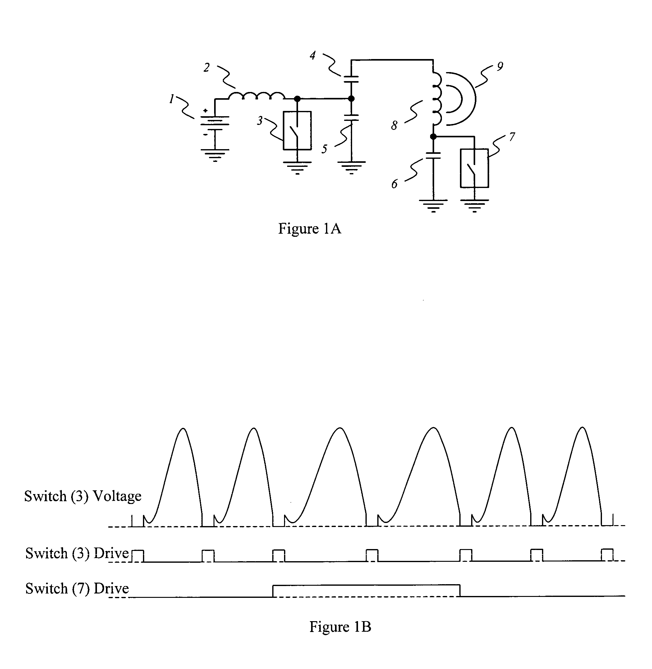
[0029] Detailed operation of an unmodulated Class-E converter used in a transmitter circuit may be further understood by referring to a United States patent issued to co-inventor Troyk (et al.), U.S. Pat. No. 5,179,511 entitled Self-regulating Class E Resonant Power Converter Maintaining Operation in a Minimal Loss Region. Referring to FIG. 1A herein, the standard Class-E converter consists of a resonant circuit comprised of inductor 8 (a coil), and capacitors 4 and 5. The frequency of operation is determined roughly by the value of inductor 8 and the value of capacitor 4 in series with capacitor 5. The resonant current in inductor 8 produces a magnetic field 9 that powers the implanted receiver electronics. MOSFET switch 3 is pulsed in synchrony with the resonant coil current by external control circuitry (not shown), thereby transferring energy from inductor 2 into the resonant circuit when the voltage at MOSFET switch 3 is substantially zero volts. This mode of operation results ...


PUM


Abstract

A system providing an inductive power and data link between an external transmitter and miniature internal receiver is presented. The system is suited to applications where the receiver must be of a small size and the system must consume very little power, such as an implanted biomedical device. The system is also compatible with systems where bi-directional communications are required. The novel transmitter and receiver form an improved forward data telemetry system. The transmitter consists of a Class-E converter with its optimum operating frequency being synchronously, instantaneously and efficiently altered in accordance with the data to be transmitted, thereby producing an FSK modulated magnetic field of substantially constant amplitude. The constant amplitude output allows for the continuous, data-independent transfer of power to the miniature receiver and its associated electronics. The present invention also represents an improvement over the high efficiency Class-E converters previously patented by the inventors. The receiver consists of a coil and an integrated rectifying system to recover operating power from the incident magnetic field, as well as an FSK demodulator whose operation is based on the multiphase comparison of charging times of integrated capacitors. The described FSK demodulator approach removes deleterious effects resulting from low-frequency changes in the transmitter frequency, and eliminates time distortion artifacts generated by circuit imbalances and asymmetries in the power recovery process. The combination of the transmitter and receiver improvements yields a reliable data transfer system unaffected by circuit imbalances and incidental variations in the amplitude and frequency of the magnetic field.

Description

BACKGROUND OF THE INVENTION [0001] This invention relates to inductively coupled data links. More particularly, the invention establishes combined power transfer and reliable “forward telemetry” data communications between an external transmitter and an internal miniature low power receiver such as might be found in an electronic medical implant, The invention described herein was developed to communicate with an implantable medical device, but may also be effectively applied to other applications, such as some RFID transponders, for which data must be sent from an external transmitter to internal device electronics. In all of these devices miniaturization is important. Therefore, optimizing the combination of power and communication transfer from a transmitter to implant or miniature internal device while maintaining small size is crucial. To accomplish this an efficient means of remotely powering and providing telemetry data to the implant, as well as a robust means of demodulatin...

Claims


Application Information

Patent Timeline
Patent Type & Authority Applications(United States)
IPC IPC(8): G06K7/00H03K9/00H04B5/00H04L27/10
CPCA61B2560/0219G06K7/0008H04B5/00H04L27/10H04B5/0031H04B5/0037H04B5/0012
Inventor TROYK, PHILIP RICHARDDEMICHELE, GLENN ANTHONY
Owner LUNA NEURO LLC
Why Eureka
Try Eureka