Method of making adaptive negative differential resistance device

Inactive Publication Date: 2005-03-24
SYNOPSYS INC
View PDF93 Cites 14 Cited by
  • Summary
  • Abstract
  • Description
  • Claims
  • Application Information

AI Technical Summary

Benefits of technology

[0085] In still other embodiments, the concentration of charge trapping sites occurs even during normal operation of the semiconductor transistor device in the fiel

Problems solved by technology

Furthermore, the prior art to date has been limited generally to devices in which the peak-to-valley ratio (PVR) is not easily adjustable.
Alternative

Method used


Image

  • Method of making adaptive negative differential resistance device
  • Method of making adaptive negative differential resistance device
  • Method of making adaptive negative differential resistance device

Examples


Embodiment Construction

[0111] A preferred embodiment of the invention is now described with reference to the Figures provided herein. It will be appreciated by those skilled in the art that the present examples are but one of many possible implementations of the present teachings, and therefore the present invention is not limited by such.

[0112] The present invention is expected to find substantial uses in the field of integrated circuit electronics as an additional fundamental “building block” for digital memory, digital logic, and analog circuits. Thus, it can be included within a memory cell, within a Boolean function unit, and similar such environments.

[0113] Brief Summary of Prior Art

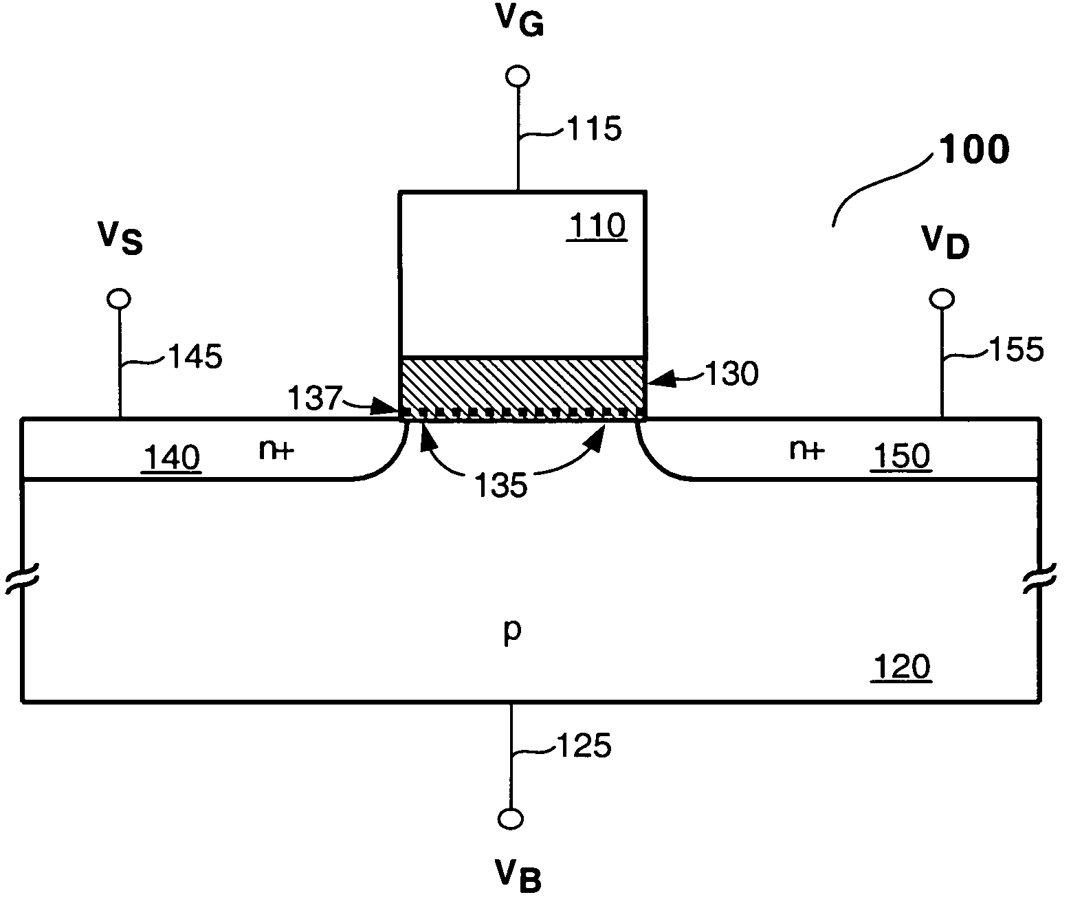
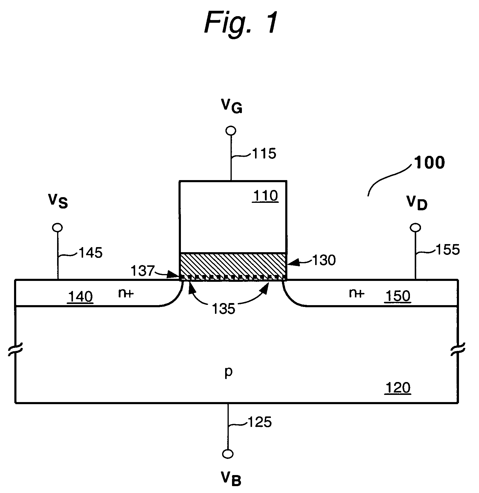
[0114]FIG. 1 shows a prior art NDR FET 100 of the type described in the King et al. applications noted earlier. This, device is essentially a silicon based MISFET that includes an NDR characteristic as well. Thus, the features of device 100 are created with conventional MOS based FET processing, modified where appropr...


PUM


Abstract

A method of controlling a negative differential resistance (NDR) element is disclosed, which includes altering various NDR characteristics during operation to effectuate different NDR modes. By changing biasing conditions applied to the NDR element (such as a silicon based NDR FET) a peak-to-valley ratio (PVR) (or some other characteristic) can be modified dynamically to accommodate a desired operational change in a circuit that uses the NDR element. In a memory or logic application, for example, a valley current can be reduced during quiescent periods to reduce operating power. Thus an adaptive NDR element can be utilized advantageously within a conventional semiconductor circuit.

Description

CROSS REFERENCE TO RELATED APPLICATIONS [0001] The present application is a continuation-in-part of the following applications which are hereby incorporated by reference as if fully set forth herein: [0002] 1. Method of Forming a Negative Differential Resistance Device; Ser. No. 10 / 314,735 (Attorney Docket No. PROG 2002-5) filed Dec. 9, 2002; [0003] 2. Process for Controlling Performance Characteristics of a Negative Differential Resistance (NDR) Device: Ser. No. 10 / 314,785 (Attorney Docket No. PROG 2002-6) filed Dec. 9, 2002; [0004] 3. Charge Trapping Device & Method of Forming the Same; Ser. No. 10 / 314,510 (Attorney Docket No. PROG 2002-7) filed Dec. 9, 2002. [0005] The present application is related to the following applications, all of which are filed simultaneously herewith, and which are hereby incorporated by reference as if fully set forth herein: [0006] 4. Integrated Circuit Having Negative Differential Resistance (NDR) Devices With Varied Peak-to-Valley Ratios (PVRs); Atto...

Claims


Application Information

Patent Timeline
IPC IPC(8): G11C11/39H01L21/265H01L21/28H01L21/336H01L21/8234H01L21/8238H01L21/8246H01L27/088H01L27/105H01L29/423H01L29/51H01L29/78
CPCG11C11/39H01L29/78H01L21/2652H01L21/28176H01L21/28185H01L21/28194H01L21/28282H01L21/823412H01L21/823462H01L21/823857H01L27/088H01L27/105H01L27/11568H01L29/42332H01L29/513H01L29/517H01L29/518H01L29/66833H01L21/265H01L29/40117H10B43/30H01L21/26513
Inventor KING, TSU-JAE
Owner SYNOPSYS INC
Why Eureka
Try Eureka