Systems and methods for monitoring and controlling water consumption

a technology of consumption system and water consumption flow, applied in the direction of lighting and heating apparatus, instruments, packaged goods types, etc., can solve the problems of frequent buildup and corrosion of mineral deposits, impair operation, and the possibility of catastrophic failure, and achieve the effect of monitoring and controlling the daily water consumption flow

Inactive Publication Date: 2005-03-31
FIMA RAOUL G
View PDF39 Cites 73 Cited by
  • Summary
  • Abstract
  • Description
  • Claims
  • Application Information

AI Technical Summary

Benefits of technology

[0013] The invention is designed to monitor and control the daily water consumption flow of all water-based systems in the home or commercial business. These include, for example, water heater, sinks, toilets, dishwashers and clothes washer, swimming pool and lawn sprinklers. The invention includes one or more electrical circuit interface modules in an electrical panel

Problems solved by technology

After a period of time, however, mineral deposit buildup and corrosion frequently take place in relief valves and the like, as a result of these periodic operations.
In time, such corrosion or scale build up may impair operation.
When this occurs, the possibility of a catastrophic failure exists.
In addition to the possibility of high pressure explosions taking place in water tanks, other conditions can also lead to significant damage to the surrounding structure.
As hot water tanks age, frequently they develop leaks, or leaks develop in the water inlet pipe or hot water outlet pipe to the tank.
If such leaks go undetected, water damage from the leak to the surrounding building structure results.
While the various systems disclosed in the prior art patents discussed above function to sense potential malfuncti

Method used


Image

  • Systems and methods for monitoring and controlling water consumption
  • Systems and methods for monitoring and controlling water consumption
  • Systems and methods for monitoring and controlling water consumption

Examples


Embodiment Construction

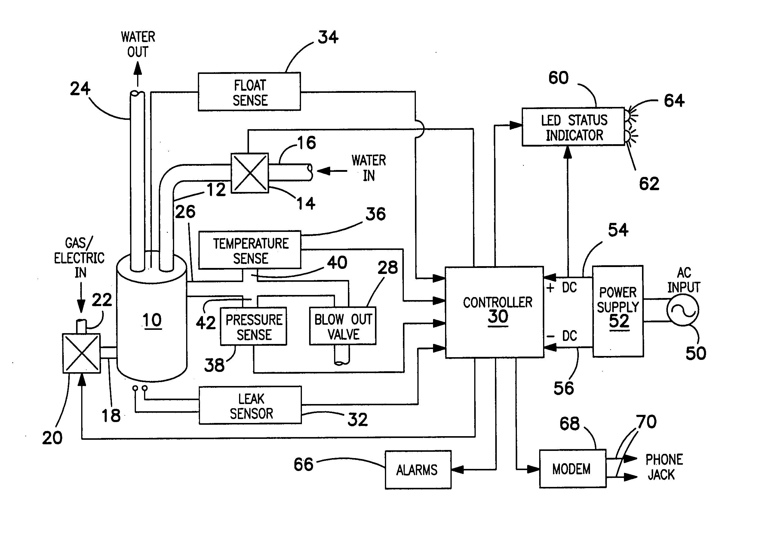
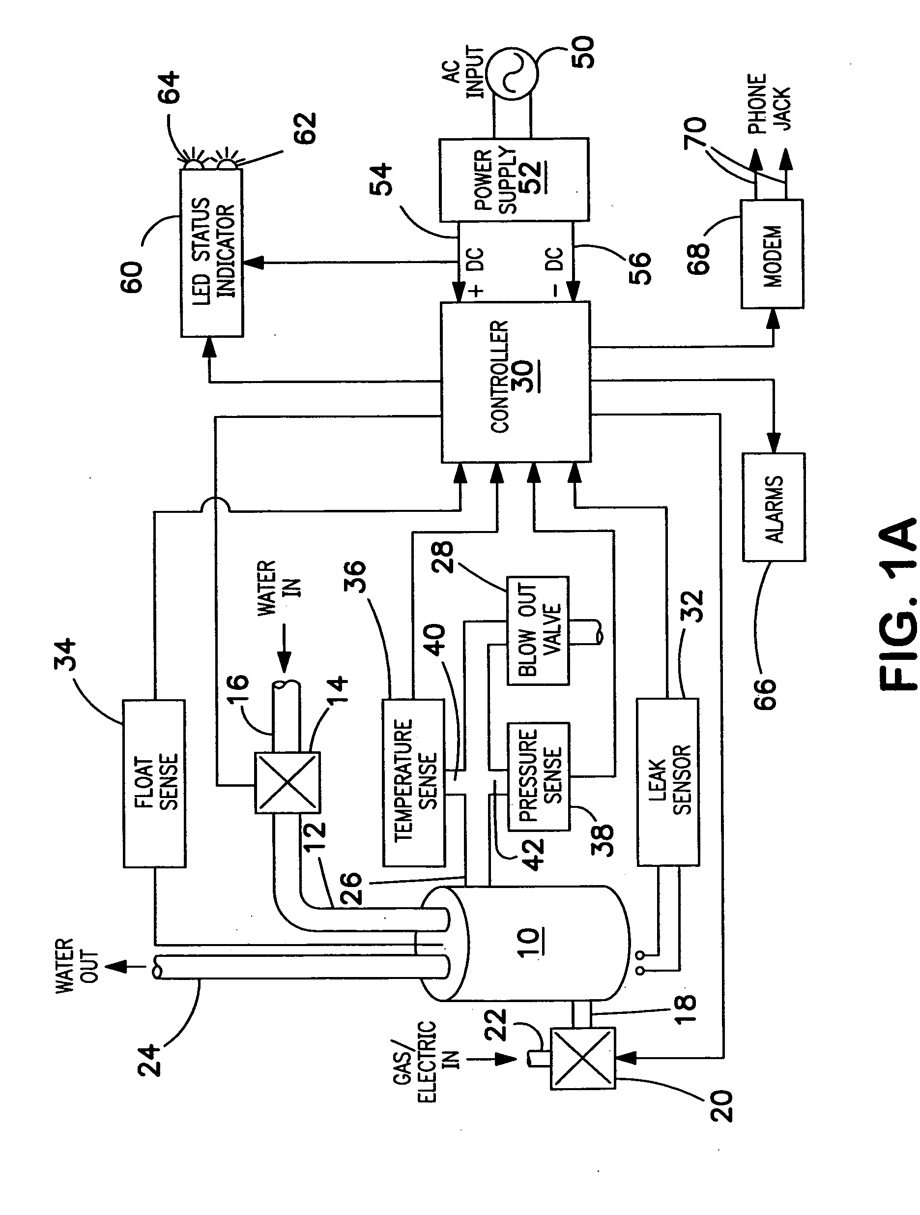
[0033] Reference now should be made to the drawings, in which the same reference numbers are used throughout the different figures to designate the same or similar components. FIGS. 1A and B are block diagrams of water monitoring systems providing comprehensive monitoring of various alarm conditions representative of malfunctioning parameters in water-based systems and the like. In addition, the system of FIG. 1A operates in response to a water appliance or system malfunction to turn off the input water supply and to disconnect the energy source supplying heat to the water appliance or system when such a malfunction occurs.

[0034] In the monitoring system shown in FIG. 1A, a hot water tank 10, which may be of any conventional type, is illustrated. The hot water tank 10 may be heated either by a gas supply or an electric supply. The system operates in the same manner, irrespective of which type of heat source is employed for the hot water tank 10. Inlet or make-up water for the hot w...


PUM

PropertyMeasurementUnit
Temperatureaaaaaaaaaa
Pressureaaaaaaaaaa
Flow rateaaaaaaaaaa

Abstract

Systems and methods for monitoring and controlling water consumption in a water-based system are disclosed using one or more sensors for generating signals indicative of the operation thereof. One or more interface modules are provided as breaker circuits for receiving the generated signals, and a fluid control device is operable for limiting the water consumption. A motherboard receives the interface modules and provides communication therebetween for information processing. Signals from the various sensors are supplied to a controller, which provides signals to status indicators, and also operates to provide alarm signals via network interfaces to remote locations and to operate an alarm. In an alternate embodiment, a water monitoring system is designed to shut off the water supply to the water device and to shut off either the electrical supply or the gas supply to the heating unit of the water device in response to sensing a malfunction through one or more of a number of different sensed parameters. These parameters include a water leak detector located beneath the water device, a water level float sensor, a temperature sensor to sense excess temperature, and a pressure sensor located in line.

Description

[0001] This application is a continuation-in-part of U.S. Utility application Ser. No. 10 / 252,350 filed 23 Sep. 2002.BACKGROUND OF THE INVENTION [0002] 1. Field of the Invention [0003] The present invention relates to the fluid consumption systems in the home and commercial environments. More particularly, the invention relates to automated controls and monitoring of such water-based systems employing methods for detecting, communicating and preventing operational failures. [0004] 2. Description of the Related Art [0005] There are various water-consuming fixtures, appliances, and systems in both residential and commercial installations. Typical water-based systems include sinks, toilets, dishwashers, washing machines, water heaters, lawn sprinklers, swimming pools and the like. For example, hot water tanks include a heating element located at the bottom of the tank, with a hot water outlet pipe and a make-up water inlet pipe connected through the top of the tank. In water tanks a th...

Claims


Application Information

Patent Timeline
IPC IPC(8): B65B1/04B65B1/30B65D1/04F24H9/20G01M3/00G01M3/18G01M3/28
CPCF24H9/2007F24H9/2021G01M3/2815G01M3/186G01M3/2807G01M3/002F24H15/414F24H15/242F24H15/248F24H15/395F24H15/37F24H15/31F24H15/212F24H15/104F24H15/12
Inventor FIMA, RAOUL G.
Owner FIMA RAOUL G
Why Eureka
Try Eureka