Binding structure of refractory sleeve for inner hole of nozzle for continuous casting

Active Publication Date: 2005-03-31
KROSAKI HARIMA CORP +1
View PDF5 Cites 4 Cited by
  • Summary
  • Abstract
  • Description
  • Claims
  • Application Information

AI Technical Summary

Benefits of technology

[0007] It is an object of the present invention to provide a bonding structure between a nozzle body of a continuous casting nozzle and a CaO-containing refractory sleeve inserted into the nozzle body to prevent alumina deposit, which is capable of preventing the expansion of the refractory sleeve from excreting adverse affects on the nozzle body.
[0008] It is another object of the present invention to provide a bonding structure capable of preventing the refractory sleeve attached to the nozzle body from being detached therefrom even if the refractory sleeve is thermally expanded.
[0009] It is still another object of the present invention to provide a continuous casting nozzle capable of effectively reducing alumina deposit and contributing to stable casting operation and improvement of slab quality.
[0012] While a continuous casting nozzle having a nozzle body and a CaO-containing refractory sleeve combined with the nozzle body may be prepared by integrally molding the sleeve and the nozzle body or by inserting the sleeve into the nozzle body and adhesively bonding them together, the adhesively bonded structure has a spalling resistance superior to that of the other structure. It is believed that the excellent spalling resistance comes from the adhesive joint having a function of absorbing or relaxing a thermal stress due to exponential expansion of the sleeve caused by molten steel flowing into the inner hole of the sleeve during use of the nozzle.
[0019] In case of combinationally using a refractory aggregate containing MgO as a primary component, and 30 mass % or less of one or more substances including alumina and / or aluminum in the form of Al2O3, a spinel is created due to thermal load from molten steel. Then, due to expansion of the aggregate in connection with the creation of the spinel, the porosity of the joint is reduced, and the bonding strength between the nozzle body and the sleeve is increased. The creation of the spinel has no adverse affect on spalling likely to occur at the initiation of the pouring of molten steel because the spinel is gradually created after a thermal stress generated at the initiation of the pouring is relaxed. However, if the substances to be combined in the form of Al2O3 become greater than 30 mass %, a low-melting-point substance will be undesirably created at a large amount through the reaction with CaO contained in the sleeve.
[0020] While the thickness of the joint is not limited to a specific value, it is preferably set in the range of 0.5 to 2.5 mm in view of the stress relaxation and bonding functions of the joint. In case where the thickness of the joint is set at a relatively small value, it is preferable to set the porosity of the joint at a relatively large value so as to provide an enhanced stress relaxation function. In case where the thickness of the joint is set at a relatively large value, it is preferable to set the porosity of the joint at a relatively small value so as to provide an enhanced bonding function.

Problems solved by technology

A non-metallic inclusion in steel, such as alumina, which is deposited on the inner hole of an immersion nozzle during a steel continuous casting process, has adverse affects on the quality of a final product.
Moreover, in the casting for long hours, the deposit on the inner hole of a nozzle, such as an immersion nozzle, causes clogging of the inner hole, which leads to difficulty in continuing the casting operation or deterioration in productivity.
In this technique, if the argon gas is injected at an excessive amount, resulting gas bubbles will be incorporated into slabs to cause the formation of pinholes in a mold or defect in a steel product.
Thus, the gas has to be injected at a limited amount, and consequently an adequate effect cannot be always obtained.
Currently, the ZCG-base material has put into practical use only in a part of nozzles, but not come into general use.
One of the reasons is in that if steel has a relatively large amount alumina inclusion, an adequate anti-alumina-deposit effect cannot be obtained.
However, if the amount of CaO is increased, the ZCG-base material will inevitably have a larger thermal expansion coefficient.
Thus, the material applied to the body of a nozzle is likely to cause thermal spalling.
Even if the material is applied to only an inner hole portion of a nozzle, the body of the immersion nozzle will be likely to be pressed and cracked by the thermally expanded material.
As with the aforementioned publication, this nozzle has a problem of cracks of the nozzle body caused by expansion of the refractory sleeve due to a relatively large thermal expansion coefficient of the lime-based refractory material.

Method used


Image

  • Binding structure of refractory sleeve for inner hole of nozzle for continuous casting
  • Binding structure of refractory sleeve for inner hole of nozzle for continuous casting

Examples


Embodiment Construction

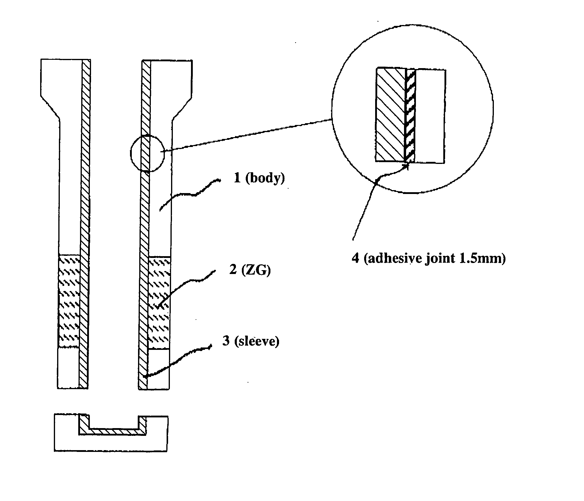
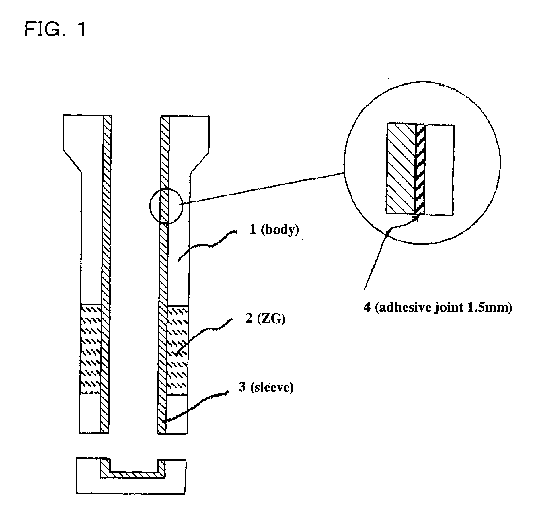
[0022] In an immersion nozzle illustrated in FIG. 1, the reference numerals 1, 2, 3 and 4 indicates a nozzle body, a ZG composition used on a slag line, a sleeve, and an adhesive joint, respectively.

[0023] A to F in the following Table 1 indicates examples of a composition for use in each portion of the immersion nozzle.

TABLE 1Type of CompositionABCDEFCompoundingC252520—25—RatioAl2O375—————(mass %)MgO—75——3540ZrO2——6070——CaO——20304060

[0024]

TABLE 2ComparativeExampleInventive Example11234567Material of BodyAAAAAAAAMaterial of SleeveCCCCCCCCPorosity of Joint1015203045607590SpallingCracks inX◯◯◯◯◯◯◯TestBodyDetachment◯◯◯◯◯◯◯◯of sleeveComparativeComparativeExampleInventive ExampleExample238910111213144Material of BodyAAAAAAAAAAMaterial of SleeveCDDDDDDDDDPorosity of Joint95101520304560759095SpallingCracks in◯XΔ◯◯◯◯◯◯◯TestBodyDetachmentX◯◯◯◯◯◯◯◯Xof sleeve

In the test result,

◯: no defect,

Δ: occurrence of minor defect,

X: occurrence of serious defect

[0025]

TABLE 3ComparativeExampleInvent...


PUM

PropertyMeasurementUnit
Fractionaaaaaaaaaa
Percent by massaaaaaaaaaa

Abstract

Disclosed is a bonding structure between a nozzle body of a continuous casting nozzle and a refractory sleeve inserted into the nozzle body, wherein the refractory sleeve contains 20 mass % or more of CaO. An adhesive including a mixture of a refractory aggregate and a binder is applied to a joint zone defined in either one of at least a portion of the outer peripheral surface of the refractory sleeve and at least a portion of the inner surface of the hollowed nozzle to which the refractory sleeve is attached, or between the inner surface of the nozzle body and the outer peripheral surface of the refractory sleeve inserted into the nozzle body. The adhesive is adjusted to have a porosity in the range of 15 to 90% after dried in the joint zone. The bonding structure has a function of relaxing a thermal stress due to exponential expansion of the refractory sleeve caused by molten steel flowing into an inner hole of the nozzle during use, so as to prevent the detachment of the refractory sleeve and adverse affects on the nozzle body due to thermal expansion of the refractory sleeve.

Description

TECHNICAL FIELD [0001] The present invention relates to the prevention of alumina deposit on the inner hole of a nozzle for use in continuous casting of steel, such as a submerged or immersion nozzle, upper nozzle, sliding nozzle, lower nozzle or long nozzle. In particular, the present invention relates to a bonding structure for a refractory sleeve defining the inner hole of such a nozzle to achieve that purpose. BACKGROUND ART [0002] A non-metallic inclusion in steel, such as alumina, which is deposited on the inner hole of an immersion nozzle during a steel continuous casting process, has adverse affects on the quality of a final product. In connection with strict quality recently required for steel products, a good deal of effort has been made to reduce the deposit of the non-metallic inclusion. Moreover, in the casting for long hours, the deposit on the inner hole of a nozzle, such as an immersion nozzle, causes clogging of the inner hole, which leads to difficulty in continuin...

Claims


Application Information

Patent Timeline
IPC IPC(8): B22D41/54C04B35/01C04B35/043C04B35/06C04B35/103C04B35/482C04B35/66
CPCB22D41/54C04B2237/708C04B35/013C04B35/043C04B35/06C04B35/103C04B35/482C04B37/003C04B37/005C04B2235/3206C04B2235/3208C04B2235/3217C04B2235/48C04B2235/77C04B2237/06C04B2237/064C04B2237/068C04B2237/34C04B2237/343C04B2237/348B32B2315/02B22D11/10C04B35/66B22D41/50
Inventor OGATA, KOJI
Owner KROSAKI HARIMA CORP
Why Eureka
Try Eureka