Q-quenching super-regenerative receiver

a super-regenerative receiver and receiver technology, applied in the field of radio frequency receivers, can solve the problems of low-cost and sensitive radio frequency receivers, keep such receivers out of the mass market, and current technology solutions are fairly expensive, so as to reduce the noise of quenching and regenerative receivers. , the effect of reducing the radiated noise of the receiver circuit and reducing the cos

Active Publication Date: 2005-03-31
MICROCHIP TECH INC
View PDF9 Cites 54 Cited by
  • Summary
  • Abstract
  • Description
  • Claims
  • Application Information

AI Technical Summary

Benefits of technology

[0015] A technical advantage of the present invention is reduced quench noise. Another technical advantage is maximum sensitivity at the onset of oscillation. Another technical advantage is fixed biasing of the active amplifier circuit. Another technical advantage is substantially linear Q with varying signal strength. Another technical advantage is a fixed and limited oscillator amplitude. Still another technical advantage is a variable frequency output. Yet another technical advantage is no multiplication of control noise through the active amplifier circuit. Another technical advantage is the quench switch is referenced to a low impedance (radio frequency grounded) power supply rail, thereby not requiring optical or radio frequency isolation. Another technical advantage is using a physically small magnetic coil antenna resonant in the low frequency and medium frequency reception bands. Another technical advantage is fabricating the receiver in an integrated circuit. Still another technical advantage is adding input buffering stages so as to further reduce radiated noise from the receiver circuit. Another technical advantage is low power operation. Yet another technical advantage is efficient detection of digitally modulated data signals, e.g., WWVB. Yet another technical advantage is a low cost integrated circuit solution for apparatus and systems requiring precise time.

Problems solved by technology

The market for low cost and sensitive radio frequency receivers is enormous and current technology solutions are fairly expensive.
The cost of such receivers keep this technology out of the mass markets such as energy metering and lower end consumer electronics.
However, acceptance of highly accurate and automatically set time appliances is greatly dependent upon cost and ease in implementation.
However, complex and expensive receiving equipment is presently used to receive the time signals from the NIST radio stations.
Existing super-regenerative receivers use controlled quenching that introduce unwanted noise into the resonant tank circuit of the super-regenerative receiver, thus reducing the ultimate sensitivity of the receiver.
In addition, the sensitivity of the super-regenerative receiver is non-linear due to the controlled quenching.
Alternatively, super-regenerative receivers require a large number of active and passive devices to realize a practical and sensitive solution which is both expensive and difficult to implement in an integrated circuit.
In addition, implementation of a low frequency (LF) reception super-regenerative receiver is problematic in that the quench frequency and the carrier frequency are relatively close to one another, leading to difficulties in designing for reduced cross modulation (distortion), and thus unwanted noise.
Another problem with LF passive quenching is the large capacitor and inductor values required for implementation, these components take up space and increase cost.
Super-regenerative receivers also have the unwanted characteristic that the quenching action radiates unwanted noise and thereby causes other super-regenerative receivers to “hear” one another when placed in close proximity.
A high Q is desired at startup when “sampling” the incoming radio signal, having a low Q results in the existing regenerative receivers being noisy because they receive wide bandwidth (low Q tank circuit) noise during startup.
Another disadvantage of known regenerative receivers is that with a varying bias, the effective receiver bandwidth (Q) changes with signal strength and thus noise performance can worsen when receiving weak signals.
This approach introduces unwanted noise due to the high dv / dt square wave source, the author ties to solve this problem with excessive filtering but the ultimate sensitivity is limited.
The solution makes use of a number of active stages and the biasing and control circuitry that induces noise into the receiver and thus reduces the ultimate sensitivity.

Method used


Image

  • Q-quenching super-regenerative receiver
  • Q-quenching super-regenerative receiver
  • Q-quenching super-regenerative receiver

Examples


Embodiment Construction

[0026] Referring now to the drawings, the details of exemplary embodiments of the present invention are schematically illustrated. Like elements in the drawing will be represented by like numbers, and similar elements will be represented by like numbers with a different lower case letter suffix.

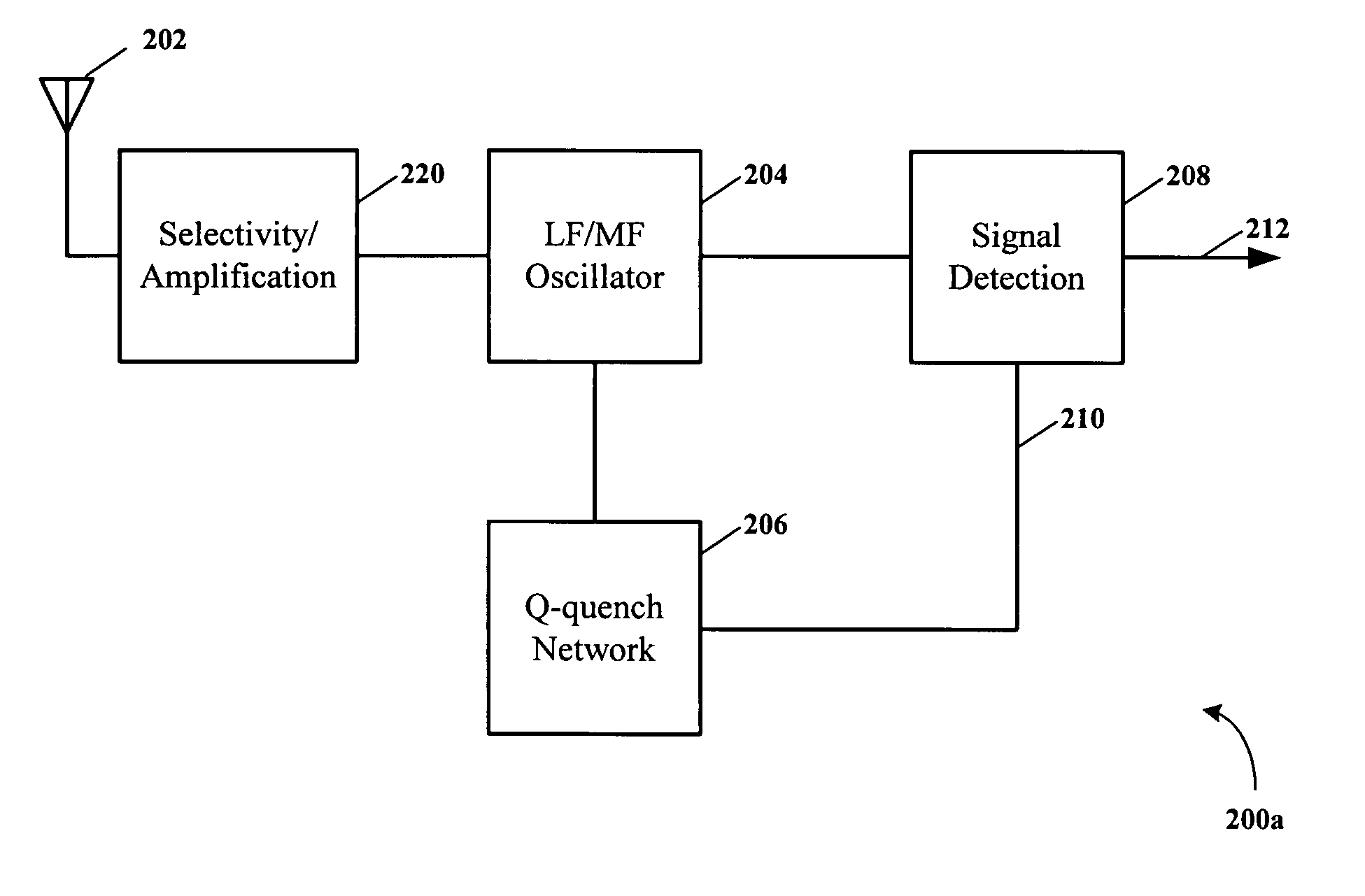
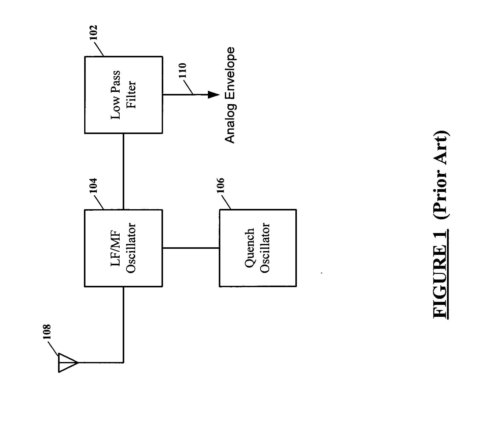
[0027] Referring to FIG. 1, depicted is a schematic block diagram of prior art super-regenerative receiver. Regenerative detectors are basically oscillators to which an input signal has been coupled. In a straight regenerative circuit, the input signal is coupled to the detector and then “regenerated” to very high levels by feeding back in phase a portion of the output signal of the detector to the input of the detector, until just before or just at a critical point where a self sustaining oscillation begins. A super-regenerative receiver uses an oscillating regenerative detector that is periodically shut off or “quenched.” Super-regeneration allows the received signal to be regenerated over...


PUM


Abstract

A super-regenerative receiver uses controlled Q-quenching and may limit the resonant tank circuit amplitude by loading the tank circuit as soon as regenerative oscillation is detected. An amplitude detector is coupled to the regenerative amplifier and controls a Q loading circuit coupled to the tank circuit of the regenerative amplifier. The amplitude detector turns on the Q loading circuit which then stops the regenerative amplifier from oscillating, and the Q-loading remains on for a brief time to insure that the regenerative amplifier has stopped oscillating. After the brief time, the Q loading circuit is turned off and the regenerative amplifier goes into oscillation again. This cycle repeats controllably over and over, resulting in a lower self-induced noise floor and improved received signal sensitivity. The super-regenerative receiver may be used in the very low frequency (VLF), low frequency (LF), medium frequency (MF), high frequency (HF), very high frequency (VHF) and super high frequency (SHF) ranges to receive continuous wave (CW), amplitude modulated (AM) and frequency modulated (FM) radio signals.

Description

FIELD OF THE INVENTION [0001] The present invention relates generally to radio frequency receivers, and more particularly to low power and cost super-regenerative receivers. BACKGROUND OF THE INVENTION TECHNOLOGY [0002] The market for low cost and sensitive radio frequency receivers is enormous and current technology solutions are fairly expensive. Low frequency (LF) receivers are used for self-setting clocks that receive the National Institute of Standards and Technology (NIST) WWVB time information and are used in high-end consumer and industrial applications. The cost of such receivers keep this technology out of the mass markets such as energy metering and lower end consumer electronics. [0003] Various radio frequencies are used to transmit this time standard. The NIST radio station WWVB transmits at a very low frequency (VLF) of 60 kHz and effectively distributes standard time information to better than one second throughout the North American continent. Other VLF time standard...

Claims


Application Information

Patent Timeline
Patent Type & Authority Applications(United States)
IPC IPC(8): H03D11/02H03D11/06H04B1/30
CPCH03D11/02H04B1/30H03D11/06H04B1/16
Inventor LOURENS, RUAN
Owner MICROCHIP TECH INC
Why Eureka
Try Eureka