Self-limited metal recess for deep trench metal fill

a metal recess and deep trench technology, applied in the direction of basic electric elements, electrical apparatus, semiconductor devices, etc., can solve the problems of reducing the efficiency of etching, so as to achieve enhanced etch rate, reduce the cost of etching, and save a number of manufacturing process steps

Inactive Publication Date: 2005-03-31
IBM CORP
View PDF18 Cites 4 Cited by
  • Summary
  • Abstract
  • Description
  • Claims
  • Application Information

AI Technical Summary

Benefits of technology

[0006] The chlorine-based chemistry is substantially fluorine free (e.g., has less than 5% fluorine). The etching process uses a decoupled power source that is substantially free of bias (e.g., uses a decoupled power source with a bias power of less than 100 W). Thus, the energetic ion bombardment is extremely low, and the etch rate is primarily (>90%) isotropic. Some low self-bias is present, as required to prevent micro-masking of the etch front and enhanced etch rate.
[0007] The etching process is rate-limited by availability of radicals (e.g. Cl, Cl+), due to the low bias highlighted above. Inside the high aspect ratio trench, the diffusivity of these radicals is limited by Knudsen flow, and a gradient in available radicals occurs from the entrance of the trench to the bottom. As the reactive gas in the trench is exposed to TiN, the reaction becomes rate-limited by the local reactant concentration, or mass transfer limited due to the gradient in the trench. Therefore, the invention does not need the polysilicon plug to protect the sides of the titanium nitride columns. Further, by altering the recess etch in this manner, the invention makes the etch more selective to silicon nitride and polysilicon (doped or undoped). By eliminating the polysilicon plug, the invention saves a number of manufacturing process steps.

Problems solved by technology

The etching process is rate-limited by availability of radicals (e.g. Cl, Cl+), due to the low bias highlighted above.
As the reactive gas in the trench is exposed to TiN, the reaction becomes rate-limited by the local reactant concentration, or mass transfer limited due to the gradient in the trench.

Method used


Image

  • Self-limited metal recess for deep trench metal fill
  • Self-limited metal recess for deep trench metal fill
  • Self-limited metal recess for deep trench metal fill

Examples


Embodiment Construction

[0015] The present invention and the various features and advantageous details thereof are explained more fully with reference to the non-limiting embodiments that are illustrated in the accompanying drawings and detailed in the following description. It should be noted that the features illustrated in the drawings are not necessarily drawn to scale. Descriptions of well-known components and processing techniques are omitted so as to not unnecessarily obscure the present invention.

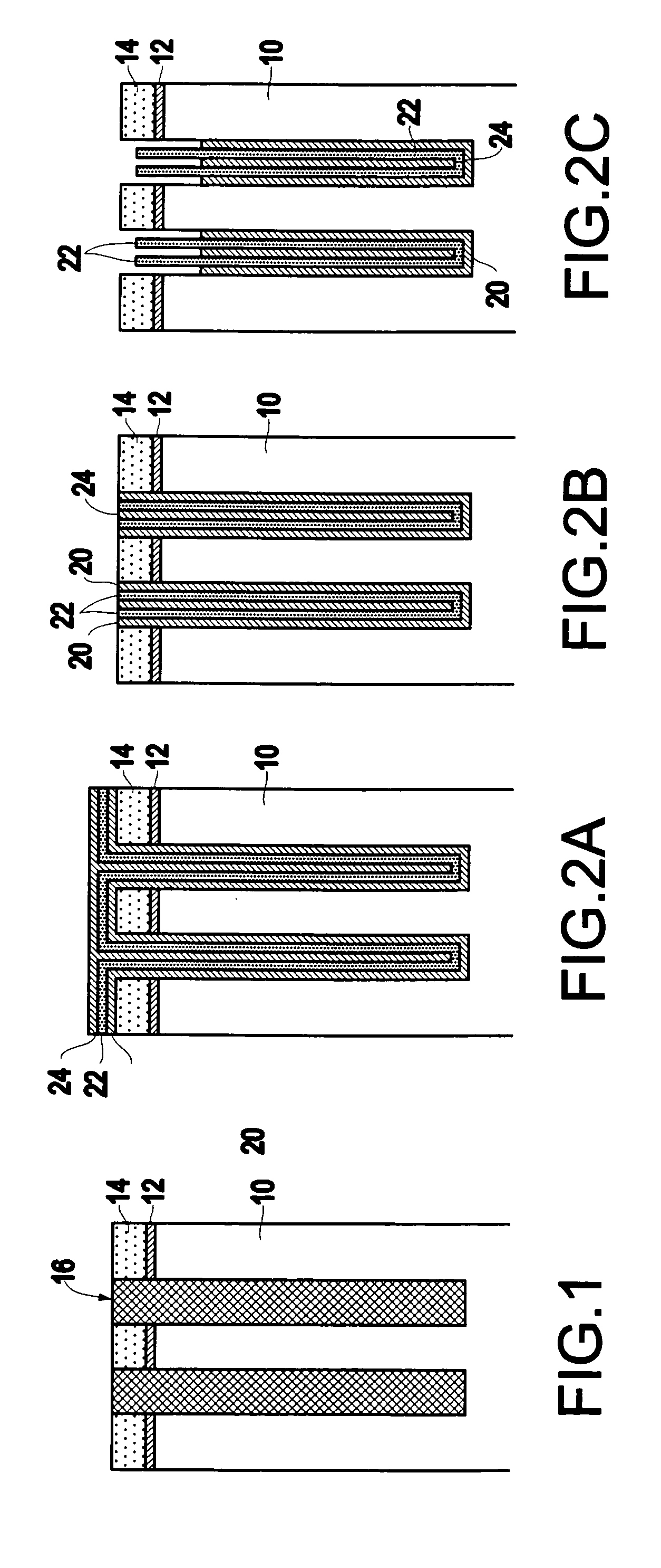
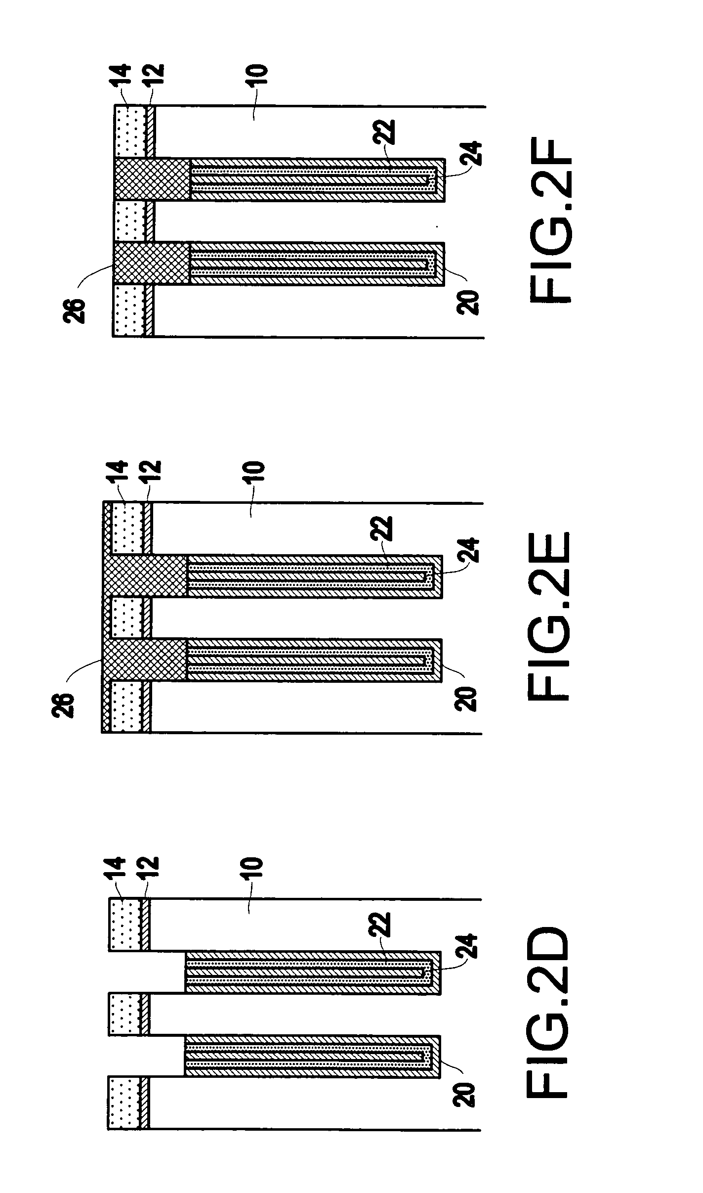
[0016] The decrease in the opening size of the trench with the concurrent increase in trench depth dramatically increases the aspect ratio (defined as depth / opening size) of the trench, increasing the complexity of the trench patterning process. Moreover, as the aspect ratio of the trench increases, the device speed generally increases concurrently, requiring a faster read / write time.

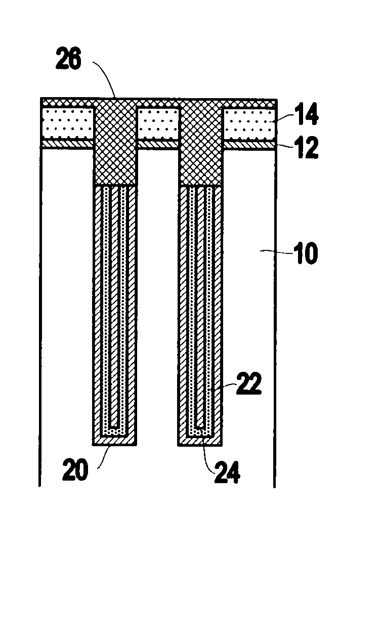
[0017]FIG. 1 illustrates a deep trench capacitor formed in a substrate 10, such as a single crystal silicon substrate. The...


PUM

PropertyMeasurementUnit
bias poweraaaaaaaaaa
sizesaaaaaaaaaa
trench depthsaaaaaaaaaa

Abstract

Disclosed is a method of manufacturing a deep trench capacitor structure that forms a trench in a substrate, lines the trench with a polysilicon liner, and forms titanium nitride columns along the polysilicon liner. The method etches the titanium nitride columns using chlorine-based dry chemistry that is substantially isotropic. This etching process removes the upper portion of the titanium nitride columns without affecting the polysilicon liner. The etching process attacks only in the uppermost portion of the titanium nitride columns such that, after the etching process is completed, the remaining lower portions of the titanium nitride columns are substantially unaffected by the etching process. Then, the method fills the space between the titanium nitride columns and the upper portion of the trench with additional polysilicon material. The process of filling the space simultaneously forms a polysilicon plug and polysilicon cap.

Description

BACKGROUND OF INVENTION [0001] 1. Field of the Invention [0002] The present invention generally relates to a process for manufacturing deep trench capacitors and more particularly to an improved etching process that etches titanium nitride trench conductors more effectively than conventional manufacturing methods. [0003] 2. Description of the Related Art [0004] In the state of the art semiconductor manufacturing, trench capacitors may be formed to store electrical charge. As the miniaturization of the semiconductor devices progresses, the feature size of the storage trench has correspondingly shrunk. State of the art memory devices today use trenches with opening sizes of less than 120 nm. A large amount of charge must be placed into each trench to compensate for charge leakage out of these trenches. Thus, the retention time of the memory device scales with the total current stored in each trench. Since the opening dimension of these trenches reduces with feature size, the available...

Claims


Application Information

Patent Timeline
Patent Type & Authority Applications(United States)
IPC IPC(8): H01L21/285H01L21/3213H01L21/8242
CPCH01L21/28568H01L27/10861H01L21/32136H10B12/038
Inventor EDLEMAN, NIKKI L.WISE, RICHARD S.
Owner IBM CORP
Why Eureka
Try Eureka