
Electrophotographic photoconductor and methods therefor

a photoconductor and electrophotography technology, applied in the direction of electrographic process, instruments, corona discharge, etc., can solve the problems of prone to solvent cracks or cracks, prone to solvent cracks, drawbacks, etc., to maintain the electrophotographic performance of the photoconductor, improve the resistance to solvent crack formation, and improve the effect of image quality

Active Publication Date: 2005-04-14
FUJI ELECTRIC CO LTD
View PDF4 Cites 20 Cited by
  • Summary
  • Abstract
  • Description
  • Claims
  • Application Information

AI Technical Summary

Benefits of technology

Therefore, an object of the invention is to provide an improved resin binder used in the photosensitive layer, and to provide an electrophotographic photoconductor that limits generation of cracks in the process of recycling a photoconductor drum and peripheral members and in the liquid development process, and thereby produces an excellent image. Another object of the invention is to provide a method to manufacture such a photoconductor.
The inventors of the invention have studied resins that are highly resistant to solvent cracks. The inventors explored polyarylate resin types and found that the use of a resin binder of polyarylate resin with a relatively high proportion of an isophthalic acid structure achieves excellent resistance to solvent cracks and is highly soluble in a solvent suitable as a coating liquid for a photoconductor. These resin binders have been found to improve the stability of the coating liquid for photoconductors and achieve electrophotographic photoconductors with good electric performance. The invention has been accomplished based on the findings.
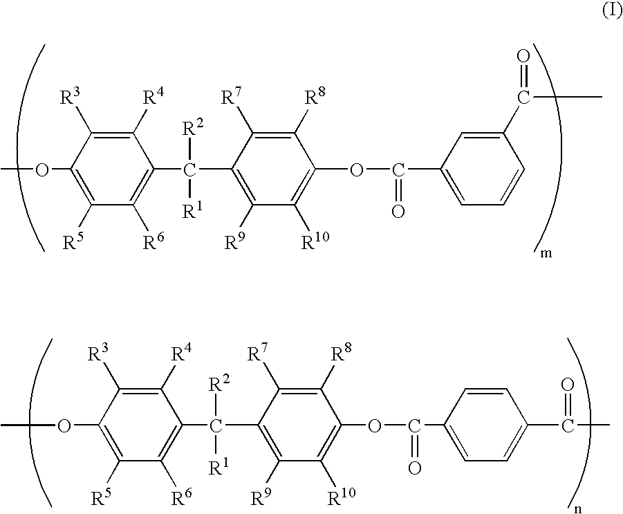
The invention uses a resin binder in a photosensitive layer, the resin binder being a polyarylate resin that comprises the above-specified structural units, and improves resistance to solvent crack formation while maintaining the electrophotographic performance of the photoconductor. Consequently, an electrophotographic photoconductor is provided that produces favorable images. The bisphenol A type polyarylate resin is particularly effective in avoiding generation of cracks. The use of polyarylate resin as a resin binder has been previously disclosed (see Japanese Unexamined Patent Application Publication Nos. S55-058223, S56-135844, H10-288845, 2002-148828, and 2002-174920). A ratio of the terephthalic acid moiety to the isophthalic acid moiety has been disclosed in Japanese Unexamined Patent Application Publication Nos. H10-288845 and 2002-148828. However, the above-mentioned disclosed Japanese Patent Documents are directed to obtaining resistance to wear or stability of a coating liquid. In contrast, this invention is directed to improvements in the resistance to the formation of solvent cracks. Therefore, this invention specifies a unique range of the ratio of the terephthalic acid moiety to the isophthalic acid moiety in the polyarylate resin as represented (see above) by the formula (I). According to this invention such a specified polyarylate resin achieves both solvent crack resistance and favorable electric performance.

Problems solved by technology

However, photoconductors comprising bisphenol Z polycarbonate resin binder, have a drawback since they are liable to generate solvent cracks or cracks due to a hand contacting on the photosensitive layer.
Solvent cracks are apt to occur due to contact with cleaner solvent during cleaning of the photoconductor and the charging member.
In contact charging systems in particular, large cracks occur in the photosensitive layer if the photoconductor is subjected to contact with the charging roller after cleaning and before complete volatilization of the cleaning solvent.
In a liquid development process, there is also a problem of frequent occurrence of solvent cracks because the photoconductor directly makes contact with carrier liquid dispersing toner particles.
However, both of these disclosures do not solve the problem (see above).
Such a surface protection layer also leads to the above-mentioned problem of cracks in the surface of a photosensitive layer.

Method used

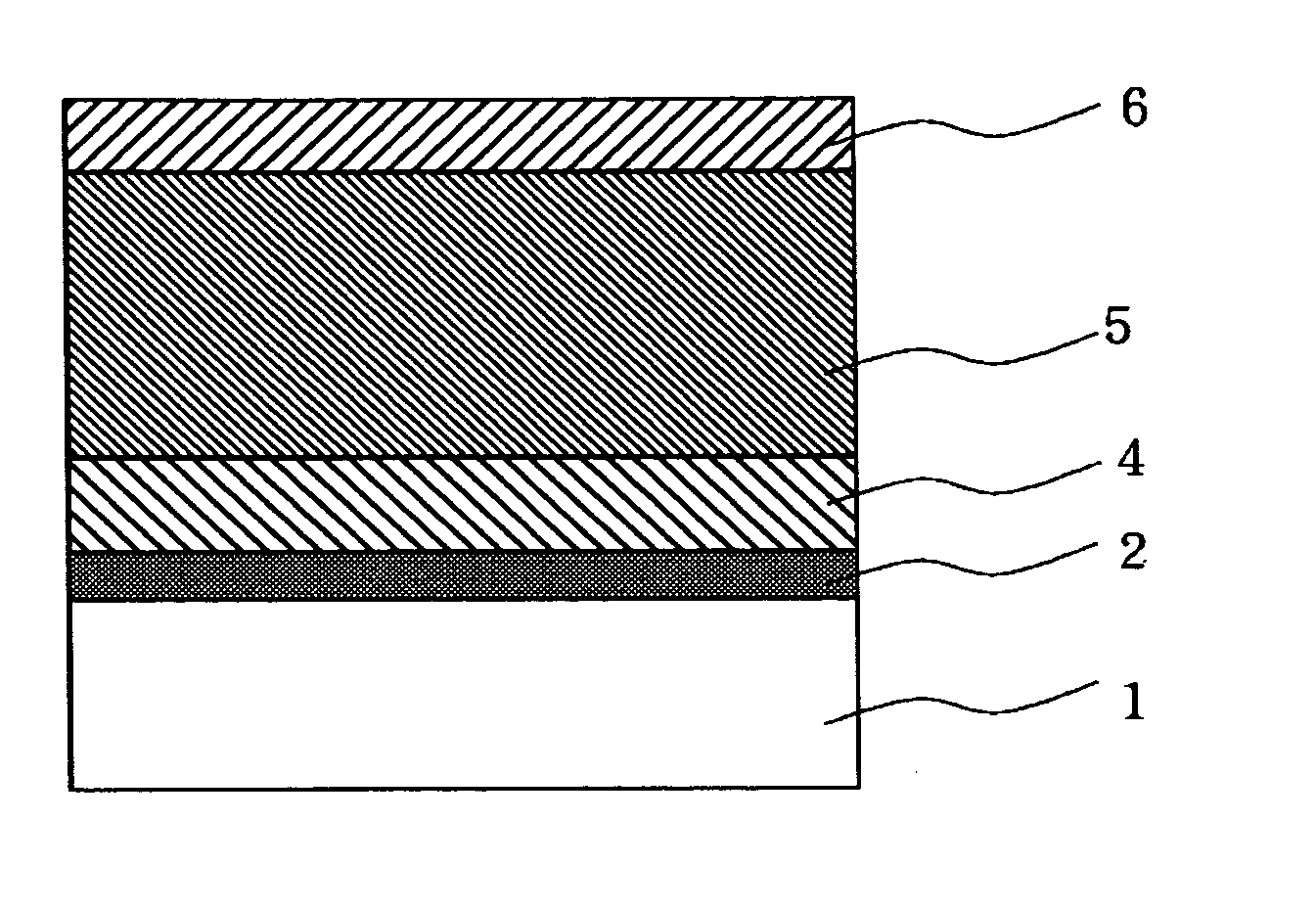

Image

  • Electrophotographic photoconductor and methods therefor
  • Electrophotographic photoconductor and methods therefor
  • Electrophotographic photoconductor and methods therefor

Examples


examples of embodiments

Specific and non-limiting examples of several embodiments of the invention are described in more in detail as follows. However, it is understood that the invention is not limited to these specific examples.

Manufacture of Polyarylate Resin

manufacturing example 1

A Manufacturing Method for Polyarylate Resin A

Ion-exchanged water 720 mL, NaOH 17.2 g, p-tert-butylphenol 0.12 g, bisphenol A 45.6 g, and tetrabutylammonium bromide 0.06 g were put into a four-port 2 liter flask. Terephthalic acid chloride 18.27 g and isophthalic acid chloride 22.33 g were dissolved in 720 mL of methylene chloride. This solution was put into the four-port flask in about 2 minutes, and then stirred for one and a half hours to promote chemical reaction. After completion of the reaction, the solution was diluted with 480 mL of methylene chloride. The aqueous phase was separated and reprecipitated with a four-fold volume of acetone. After air-drying overnight, the obtained raw material was dissolved in methylene chloride to make a 5% solution, which was then rinsed with ion-exchanged water. The reacted liquid was dropped into a four-fold volume of acetone that was vigorously agitated to cause reprecipitation. The precipitated substance was gathered by filtration and d...

manufacturing example 2

Manufacturing Method for Polyarylate Resin B

Polyarylate resin B was manufactured in the same manner as described for Manufacturing Example 1 except that the quantity of the terephthalic acid chloride was 16.24 g and the quantity of the isophthalic acid chloride was 24.36 g. The polystyrene-converted weight average molecular weight of the obtained polyarylate resin B was 103,200. The structural formula of the polyarylate resin B so obtained is shown below:


PUM

PropertyMeasurementUnit
photosensitiveaaaaaaaaaa
charge transportaaaaaaaaaa
conductiveaaaaaaaaaa

Abstract

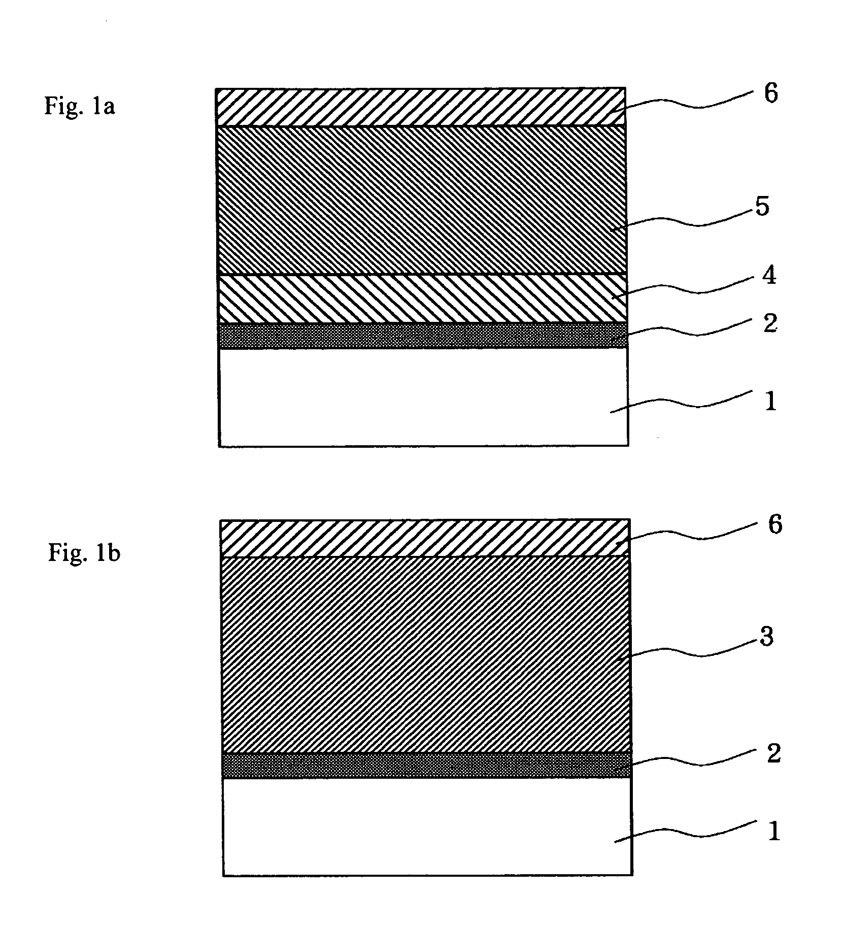
An electrophotographic photoconductor and method that seldom generate cracks even while recycling a photoconductor drum and peripheral members or in a liquid developing process, and thereby produce excellent images. The electrophotographic photoconductor includes a conductive substrate and a photosensitive layer comprising a charge generation material and a charge transport material. The photosensitive layer comprises a resin binder of polyarylate resin having structural units represented by the following formula (I): In the formula, R1 and R2 represent a hydrogen atom, an alkyl group, a cycloalkyl group, or an aryl group. R1, R2, and a carbon atom bonding to the R1 and R2 together form a cyclic structure. The cyclic structure is bonded to no more than two arylene groups. Each of R3 through R10 being a hydrogen atom, an alkyl group, a fluorine atom, a chlorine atom, and a bromine atom. The values of m and n satisfy the equation 0.5<m / (m+n)<0.7.

Description

CROSS-REFERENCE TO RELATED APPLICATION This application claims priority benefits under 35 USC § 119 of Japanese Patent Application Serial No. 2003-350001 filed on Oct. 8, 2003, the disclosure of which is incorporated by reference. BACKGROUND OF THE INVENTION 1. Field of Invention The invention generally relates to electrophotographic photoconductors and manufacturing methods, and particularly to photoconductors and methods principally comprising a conductive substrate and organic photosensitive layer and used in electrophotographic systems. 2. Background Art Electrophotographic photoconductors generally comprise a photosensitive layer having a photoconductive function laminated on a conductive substrate. Recently, organic photoconductors, which use organic materials as functional components which generate and transport charge, are being actively studied and developed for copier and printer applications. Organic photoconductors have potential benefits in flexibility of material ...

Claims


Application Information

Patent Timeline
Patent Type & Authority Applications(United States)
IPC IPC(8): G03G5/00G03G5/05G03G5/06
CPCG03G5/056C08G63/183C08G63/193G03G5/0564G03G5/0662G03G5/078G03G5/061446
Inventor KOBASHI, MASARUNAKAMURA, YOICHITAKAKI, IKUO
Owner FUJI ELECTRIC CO LTD
Learn More