Concentrating solar roofing shingle

a solar and concentrating technology, applied in thermal-pv hybrid energy generation, instruments, lighting and heating apparatuses, etc., can solve the problems of many prior art devices and systems, inability to take advantage of diffuse or scattered solar radiation, and high cost and reliability of tracking mechanisms of these prior art devices, so as to reduce the amount of relatively expensive photovoltaic materials. , the effect of dispersing excess heat into the air spa

Inactive Publication Date: 2005-04-21
STELLARIS
View PDF18 Cites 145 Cited by
  • Summary
  • Abstract
  • Description
  • Claims
  • Application Information

AI Technical Summary

Benefits of technology

[0024] A principal advantage of the present invention compared with prior art approaches is that the present invention permits a substantial reduction in the amount of relatively expensive photovoltaic material which is needed. Practical concentration ratios with the present invention can range from about 3:1 to about 8:1, depending on acceptance angles and the choice of two or three-dimensional concentration, as discussed further below.
[0025] A concentrating shingle designed for two-dimensional concentration in accordance with this invention will have multiple concentrating element profiles integrally formed in its lower planar portion. These profiles or geometries, resembling ridges or channels, will each have a lateral axis running the width of the concentrating shingle, normally aligned in an east-west direction when installed. If the profiles are designed to reach the limit for total internal reflection for a dielectric having a refraction index of about 1.5, the concentrating elements will be able to concentrate both diffuse and direct sunlight incident on them over an incidence angle of approximately 62 degrees in the plane of the shape of the concentrating element. If the axis of the profiles is aligned east to west, such 62 degree incidence angle corresponds to the acceptance angle of the altitude of the sun or other incident radiation. Radiation over the azimuth angles incident on the plane of the concentrating shingles would thus be reflected onto the absorbing surface as long as the width of the structure is wide enough to avoid losses at the edges.
[0026] The upper planar portion of a substantially light-transparent shingle in accordance with this invention serves as a supporting structure for the solar concentrating elements integrally formed in its lower planar portion. Incident sunlight striking the upper surface of such dielectric material will be refracted to a steeper angle because of the higher refractive index of the dielectric. Light will then enter the concentrating element profile in the lower part of the shingle and will be internally reflected so long as the angle of incidence of light with respect to the sides of the profile is less than the critical angle of the material.
[0027] In a preferred embodiment of the invention, a por...

Problems solved by technology

While effective within operating limits, these known solar energy concentrators are designed to concentrate direct sunlight from the almost parallel rays of the sun, but typically they are not able to also take advantage of diffuse or scattered solar radiation.
Moreover, the tracking mechanisms of these prior art devices can often be expensive and unreliable.
This is only one of several problems with and limitations of the many prior art devices and systems for utilizing solar energy.
This assembly is relatively large and would be relatively expensive to fabricate and assemble.
Although this process results in a relatively thin, shingle-like product, this fabrication involves multiple component parts and assembly steps and, as a result, is relatively costly.
Although this invention is touted as being a low cost fabrication process for making a photovoltaic device, the multiple component parts, which need to be assembled in proper alignment/orientation, a...

Method used


Image

  • Concentrating solar roofing shingle
  • Concentrating solar roofing shingle
  • Concentrating solar roofing shingle

Examples


Embodiment Construction

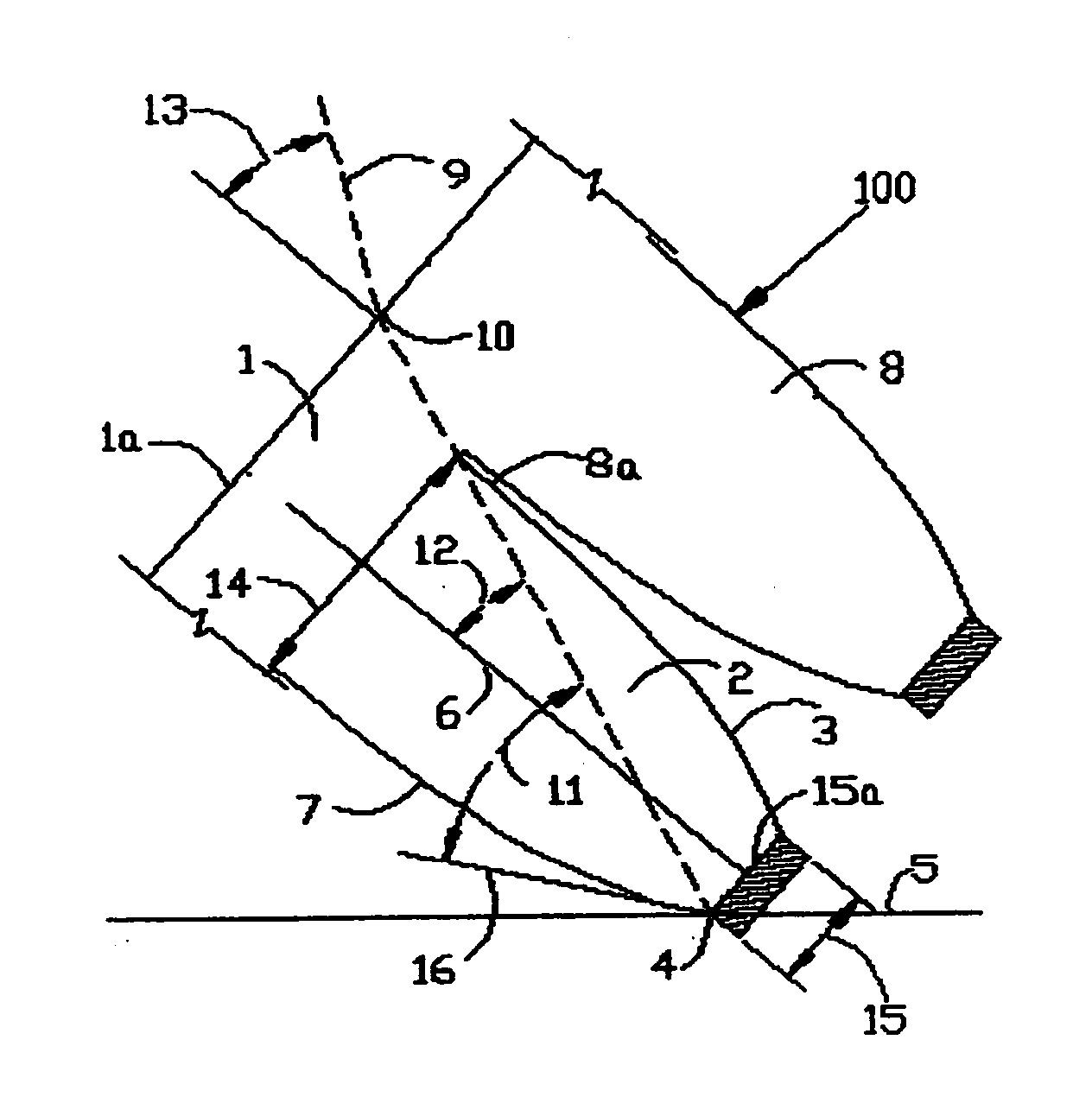
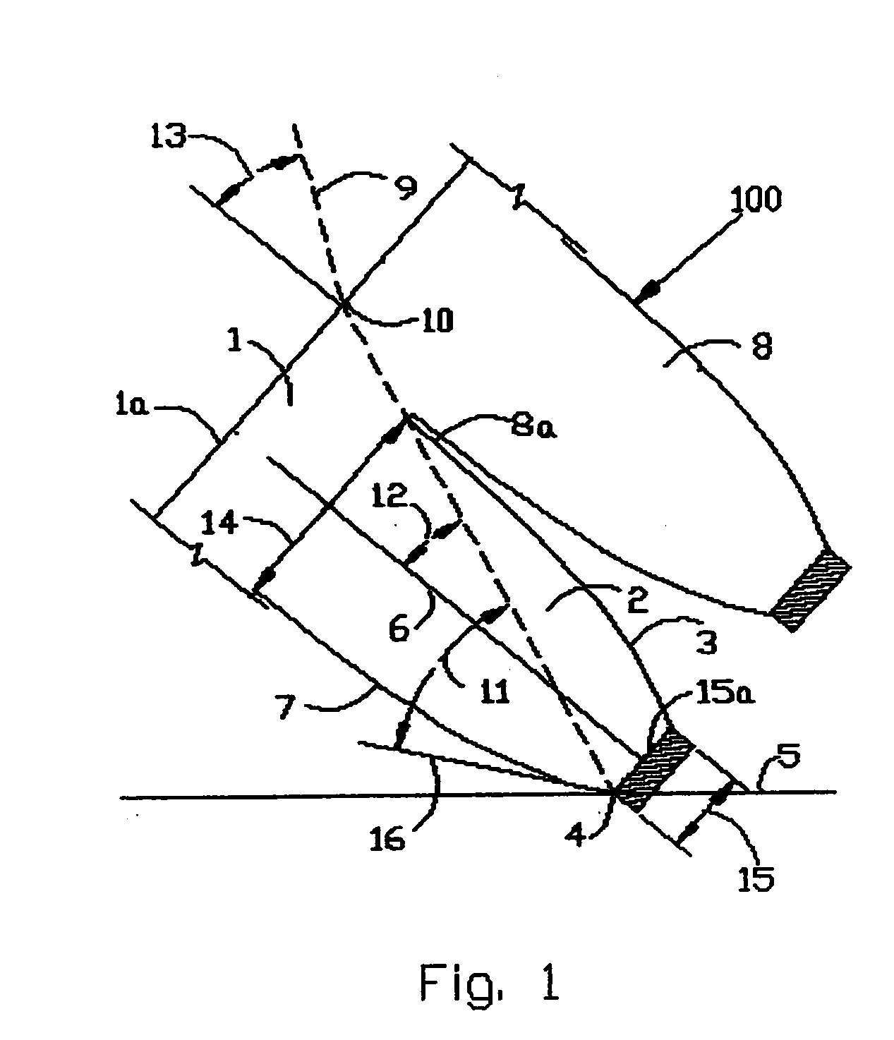
[0054] Referring to the drawings, FIG. 1 shows a section through a portion of a solar concentrating roofing shingle 100 in accordance with one embodiment of the present invention. For illustration, FIG. 1 shows two integrally-formed parabolic concentrating structures side-by-side. For purposes of example, the shingle 100 of FIG. 1 may be constructed of transparent acrylic material, although it could also be constructed of other plastic materials or glass. The embodiment of FIG. 1 is for two-dimensional concentration of light onto a photovoltaic absorber. A three-dimensional solar concentrating shingle in accordance with another embodiment of the present invention will be described in connection with subsequent drawings.

[0055] The upper glazing 1 of the concentrating shingle 100 is a continuous sheet of a substantially sunlight-transparent material that serves to protect the lower component of the shingle from the weather and to serve as a supporting structure for an integrally-form...


PUM


Abstract

This invention describes a non-imaging, non-tracking, integrally-formed solar radiation concentrator that passively concentrates both diffuse and direct solar radiation onto photovoltaic cells to produce electricity, incorporating its features into a shingle-like element useful as a roofing material and in other structural applications. The substantially transparent, solar concentrating elements of the invention may also incorporate a system to remove waste energy in the form of heat that is not utilized in the generation of electricity. The invention further provides a thermal energy recovery system including a forced convection air system for removing waste heat from the concentrating shingle assembly and using it, if desired, for building space heat or domestic water heating.

Description

BACKGROUND OF THE INVENTION [0001] Solar energy concentrators are often used to increase the effectiveness of the collection of solar radiation and to lower the cost of energy absorbing materials. Tracking solar energy concentrators have reflectors that follow the path of the sun in one or two dimensions. While effective within operating limits, these known solar energy concentrators are designed to concentrate direct sunlight from the almost parallel rays of the sun, but typically they are not able to also take advantage of diffuse or scattered solar radiation. Moreover, the tracking mechanisms of these prior art devices can often be expensive and unreliable. In order to concentrate both direct and diffuse sunlight, several different types of non-tracking, non-imaging solar energy concentrators have been developed. Compound parabolic concentrators, such as those developed by Winston and others, use mirrors with multiple parabolic cross sections to direct sunlight onto absorbing tar...

Claims


Application Information

Patent Timeline
IPC IPC(8): G02B17/08H01L25/00H01L31/048H01L31/052
CPCF24J2/10F24J2002/1014F24J2002/1023H01L31/052Y02B10/12Y02B10/20H01L31/0547Y02E10/52G02B19/0042G02B19/0028H02S20/23H01L31/0543Y02E10/40F24S23/70F24S2023/832F24S2023/834H02S40/44Y02B10/10Y02B10/70Y02E10/60
Inventor PAULL, JAMES B.
Owner STELLARIS
Why Eureka
Try Eureka