Ceramic components having multilayered architectures and processes for manufacturing the same

a ceramic component and multi-layer technology, applied in the direction of metal layered products, synthetic resin layered products, electrical equipment, etc., can solve the problems of affecting the commercial success of the product, affecting the production efficiency of the product, and reducing the thickness of the tape, so as to achieve the desired mechanical strength and electrical properties, improve the durability and strength, and improve the effect of durability and strength

Inactive Publication Date: 2005-04-21
ADVANCED CERAMICS
View PDF10 Cites 17 Cited by
  • Summary
  • Abstract
  • Description
  • Claims
  • Application Information

AI Technical Summary

Benefits of technology

[0011] The finished components have improved durability and strength as compared to monolithic ceramic components. By varying the

Problems solved by technology

Unfortunately, tape-casting processes pose severe handling problems as the thickness of the tape decreases.
Although there has been a strong desire for a more versatile process than tape casting for fabricating MLCCs, other possible fabrication methods, such has vapor deposition techniques and sol-gel techniques

Method used


Image

  • Ceramic components having multilayered architectures and processes for manufacturing the same
  • Ceramic components having multilayered architectures and processes for manufacturing the same
  • Ceramic components having multilayered architectures and processes for manufacturing the same

Examples


example 1

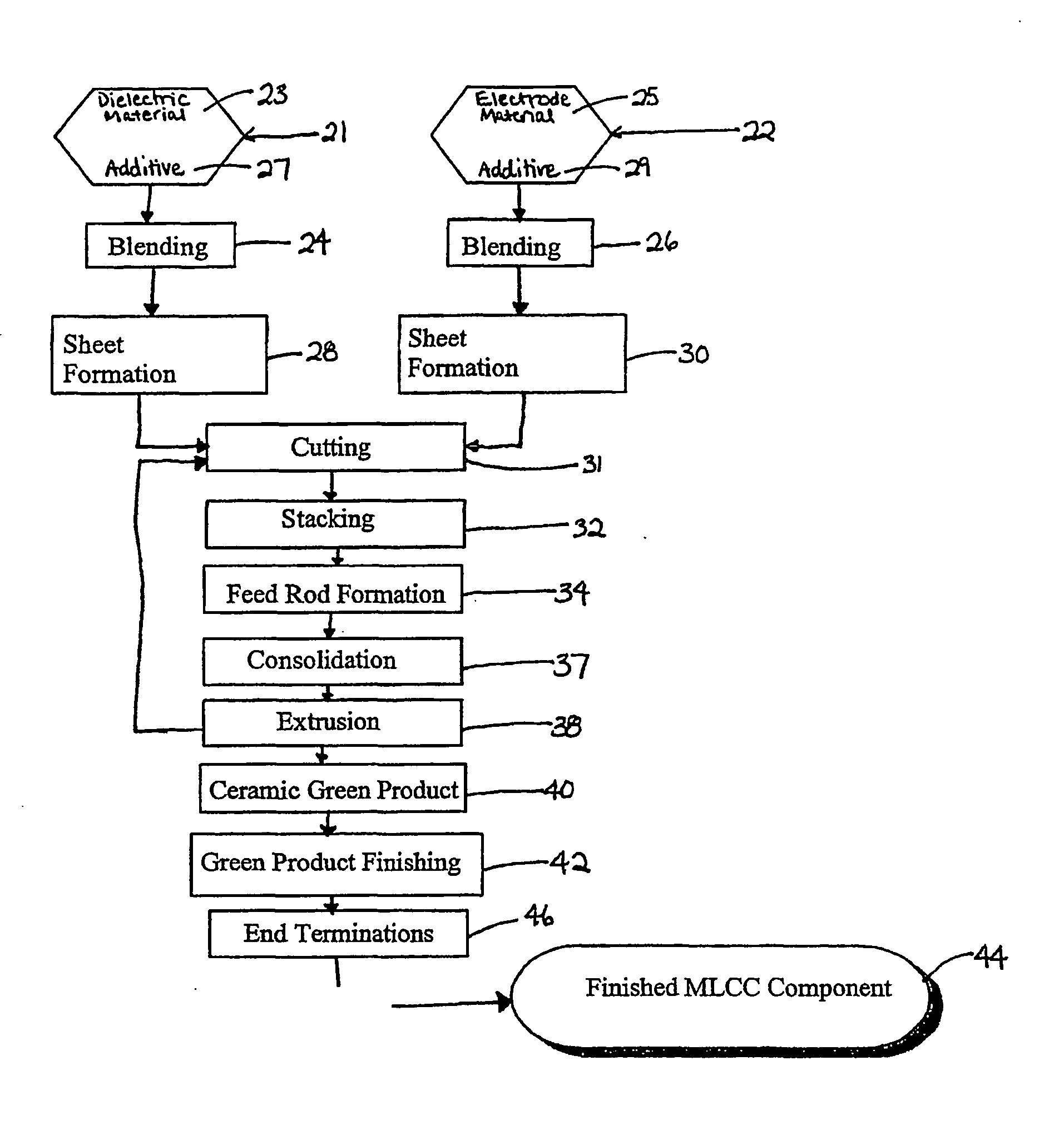
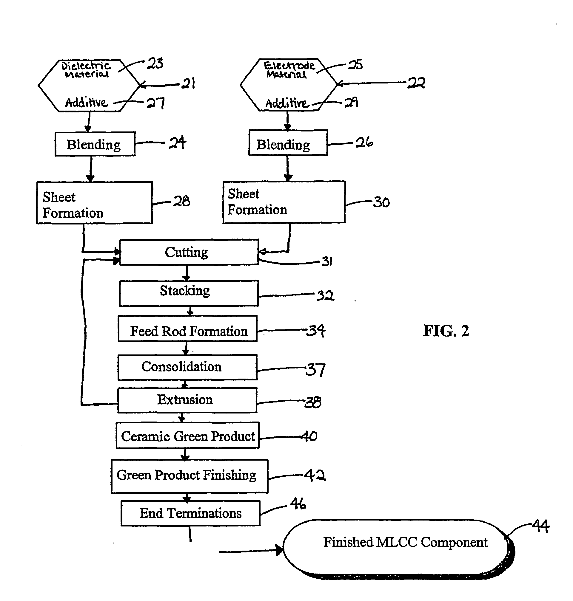
[0038] Typical dielectric composite blends and electrode composite blends are set forth below in Tables 1 and 2, respectively.

TABLE 1MaterialDensity (g / cc)Volume %BaTiO315.8545-75EEA20.9315-50HMO30.881 0-10

1BaTiO3 powder available from TAM Ceramics, Inc. as Ticon HPB grade BaTiO3

2Ethylene ethyl acrylate

3Heavy mineral oil

[0039] The batch size is 231 cc.

TABLE 2MaterialDensity (g / cc)Volume %Ni48.945-75EEA50.9325-50B-6761.06 0-10HMO70.881 0-20

4Nickel powder (<1 μm average particle size) available from Cerac, Inc.

5Ethylene ethyl acrylate

6B-67 acryloid resin

7Heavy mineral oil

The batch size is 231 cc.

[0040] Barium titanate powders were purchased from TAM Ceramics, Inc. (grades Ticon TME and Ticon HPB of BaTiO3). The HPB grade has a slightly smaller particle size (D90=2.5 μm) and were used for the BaTiO3 batches in the multi-layer coextrusions. Nickel powder in the amount of 2.5 kg (less than 1 μm average) was purchased from Cerac, Inc.

example 2

[0041] This example illustrates a method of consolidating the “green” product (MLCC chips). The thermoplastic and plasticizer binder system (additives) is effectively removed through a bake-out period. The bake-out occurs over four days in a nitrogen atmosphere where a maximum temperature of about 600° C. is reached over the four-day cycle. The final temperature of 600° C. is reached during a ramp-up period during which the temperature is raised by about 0.1 to about 0.2° C. / minute.

example 3

[0042] This example illustrates a method of sintering the “green” product (MLCC chips) to densify the ceramic capacitor. When BaTiO3 as the dielectric material and Ni as the electrode material, the MLCC chips initially may be co-fired in a nitrogen atmosphere at approximately 1150° C. This temperature is incrementally increased in order to obtain denser dielectric layers. The final co-firing schedule consists of a ramp of approximately 2° C. / minute to approximately 1275° C. with an approximately 150 minute hold at this temperature.


PUM

PropertyMeasurementUnit
Fractionaaaaaaaaaa
Fractionaaaaaaaaaa
Fractionaaaaaaaaaa

Abstract

The present invention relates to multilayered ceramic components (10) and methods of fabricating such multilayered architectures. More particularly, the present invention relates to multilayered components having a plurality of dielectric (12) and electrode material (14, 15) layers. The multilayered components are manufactured by coextrusion processes.

Description

CROSS REFERENCE TO RELATED APPLICATIONS [0001] This application is based on, and claims the benefit of, co-pending U.S. Provisional Application Ser. No. 60 / 293,596, filed on May 25, 2001, entitled “Coextrusion Melt Spinning Process for Fabricating Components Having Multilayered Architectures,” and incorporated herein by reference.[0002] The present invention was made with U.S. Government support under grant Number DASG60-01-P-0052 awarded by the U.S. Army Space and Missile Defense and under Award Number 9660898 from the National Science Foundation. Accordingly, the U.S. Government may have certain rights in the invention described herein.FIELD OF THE INVENTION [0003] The present invention relates to multilayer ceramic components, including capacitors, and methods of manufacturing such components, more particularly, coextrusion processes for manufacturing composite ceramic components having multi-layered architectures. BACKGROUND OF THE INVENTION [0004] The most common method for man...

Claims


Application Information

Patent Timeline
IPC IPC(8): B32B15/04B32B18/00B32B27/08B32B37/15B32B38/00C04B35/053C04B35/111C04B35/46C04B35/462C04B35/468C04B35/47C04B35/632C04B35/634C04B35/638H01G4/30H01L41/24
CPCB32B15/04H01L41/333B32B27/08B32B37/1054B32B37/153B32B38/0004B32B2307/202B32B2307/204B32B2311/22B32B2315/02B32B2457/00B82Y30/00C04B35/053C04B35/111C04B35/46C04B35/462C04B35/465C04B35/468C04B35/47C04B35/495C04B35/624C04B35/6261C04B35/62625C04B35/6263C04B35/6303C04B35/632C04B35/634C04B35/63424C04B35/63488C04B35/638C04B2235/3206C04B2235/3208C04B2235/3217C04B2235/3225C04B2235/3251C04B2235/449C04B2235/5436C04B2235/5445C04B2235/5454C04B2235/6021C04B2235/658C04B2235/94C04B2237/346C04B2237/40C04B2237/405C04B2237/704C04B2237/706H01G4/30H01L41/277B32B18/00H10N30/057H10N30/084B32B2457/16B32B7/12B32B27/22B32B27/306
Inventor HILMAS, GREG EPLATERO, MARLENEPOPOVICH, DRAGANRIGALI, MARK J
Owner ADVANCED CERAMICS
Why Eureka
Try Eureka